Questa versione può contenere modifiche errate. Passa all'ultima istantanea verificata.
Cosa ti serve
-
-
Rimuovi le 10 viti seguenti che fissano il coperchio inferiore al case superiore:
-
Due viti Pentalobe P5 da 2,3 mm
-
Otto viti Pentalobe P5 da 3,0 mm
-
-
-
Rimuovi attentamente il supporto ammortizzatore in gomma della ventola dal bordo del dissipatore.
-
-
-
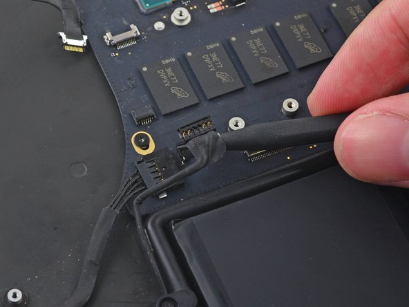
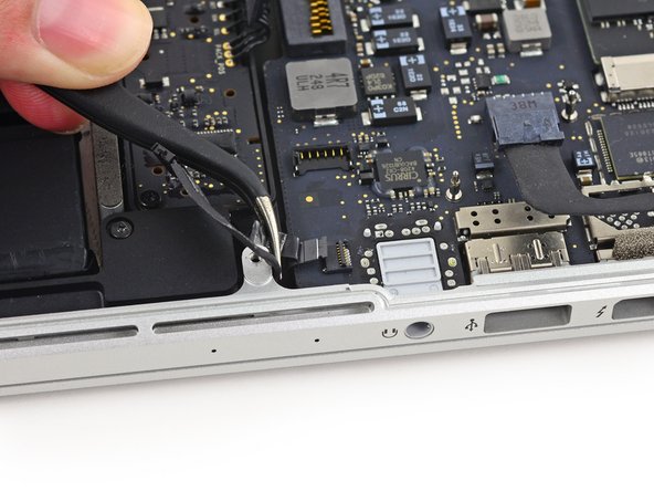
Usa la punta di uno spudger per spingere su entrambi i lati del connettore del cavo della fotocamera iSight e sfilare il connettore man mano dalla sua presa sulla scheda madre.
-
-
-
-
Svita le due viti Torx T5 da 2,1 mm che fissano la copertura del cavo della scheda I/O alla scheda madre.
-
Rimuovi la copertura del cavo della scheda I/O.
-
-
Questo passaggio è privo di traduzione. Aiuta a tradurlo
-
Remove the following screws securing the left speaker to the upper case:
-
One 5.7 mm T5 Torx screw
-
One 6.5 mm T5 Torx screw
-
One 3.8 mm T5 Torx screw
-
-
Questo passaggio è privo di traduzione. Aiuta a tradurlo
-
Lift the corner of the left speaker up and slide it toward the battery to remove it from the upper case.
-
-
Questo passaggio è privo di traduzione. Aiuta a tradurlo
-
Remove the single 3.7 mm T5 Torx screw securing the case-edge of the battery contact board.
-
-
Questo passaggio è privo di traduzione. Aiuta a tradurlo
-
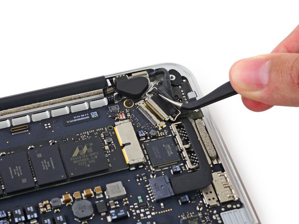
Insert the tip of a spudger under the battery-side portion of the rubber microphone cable cover to detach the adhesive there.
-
-
Questo passaggio è privo di traduzione. Aiuta a tradurlo
-
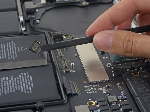
Use the flat end of a spudger to wedge the battery contact board up slightly to allow room to extract the dual microphone assembly.
-
-
Questo passaggio è privo di traduzione. Aiuta a tradurlo
-
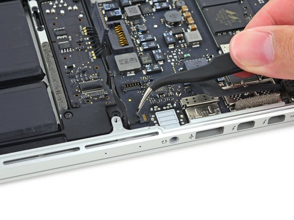
Remove the rubber microphone cover with a set of tweezers
-
-
Questo passaggio è privo di traduzione. Aiuta a tradurlo
-
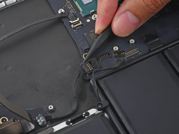
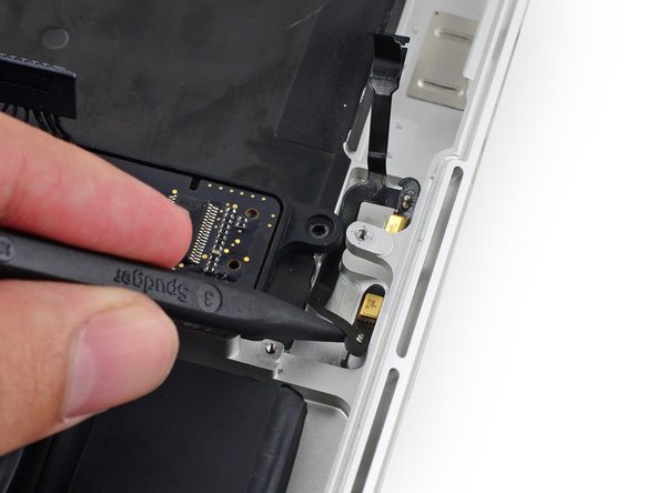
Insert the tip of a spudger underneath the connector end of the microphone ribbon cable and slide it toward the screw post to free that half from the upper case.
-
-
Questo passaggio è privo di traduzione. Aiuta a tradurlo
-
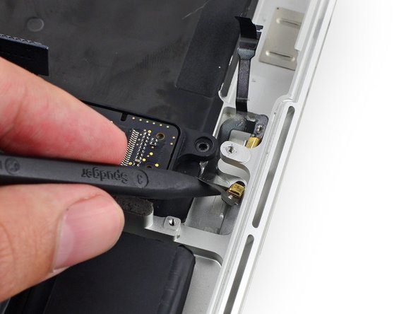
Insert the tip of a spudger under the battery-side portion of the microphone ribbon cable and slide it toward the screw post to free it from the upper case.
-
-
Questo passaggio è privo di traduzione. Aiuta a tradurlo
-
Pull the dual microphone cable assembly up and toward the logic board recess to remove it from the upper case.
-


Annulla: non ho completato questa guida.
Altre 10 persone hanno completato questa guida.

6 Commenti
Simply DISABLING the microphones can be done in 3 steps: #1, #2, #25, #26. No need to yank the logic board/fan and all that.
Many thanks for preparing / making this brilliant guide available. The mic in my Macbookpro failed for some reason and, using this guide I replaced it with a refurbished spare and saved myself $$. Every single step has been captured with specific additional detail / imagery where needed. It’s scary working with the tiny connectors but this guide gives you confidence it can be done / you can do it.
Nick Cassidy,
Where did you find a replacement? I have looked EVERYWHERE and can not find one.
Thanks!
This is the usual valuable guide to disassembly. However Steps 8-14 are NOT necessary and create added complication and potential for problems on reassembly. The motherboard can be safely removed with the fan and heatsink attached (make sure to leave the top right 3.6mm fan screw that secures to the motherboard – marked orange in Step 14 – in place). Obviously be careful not to place stress on the fan while it is only held on the one screw but otherwise there is no problem lifting and sliding the board at Step 31. I was able to get at the microphone easily after that and refitting the board was easily done too (making sure cables are not trapped underneath).
I'm slightly at a loss as to why removing the heat sink is deemed necessary unless this guide is based on another where that step is required.