Questa versione può contenere modifiche errate. Passa all'ultima istantanea verificata.
Cosa ti serve
-
-
Rimuovi le 10 viti seguenti che fissano il coperchio inferiore al case superiore:
-
Due viti Pentalobe da 2,3 mm
-
Otto viti Pentalobe da 3,0 mm
-
-
-
Rimuovi la copertura in plastica attaccata alla scheda dei contatti della batteria.
-
-
-
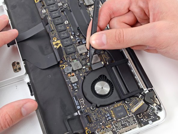
Afferra con delle pinzette l'interposer.
-
Solleval'interposer dalla scheda logica e rimuovilo.
-
-
-
Usa l'estremità piatta di uno spudger per staccare il lato destro del connettore del cavo dati della scheda I/O dal suo zoccolo sulla scheda I/O.
-
-
-
Usa l'estremità piatta di uno spudger per staccare il connettore del cavo dell'SSD dal suo zoccolo sulla scheda logica.
-
Sposta il connettore del cavo dell'SSD dove non dia fastidio.
-
-
-
Inserisci l'estremità piatta di uno spudger per sollevare, staccandolo, il connettore del cavo del jack altoparlanti dal suo zoccolino sulla scheda logica.
-
-
-
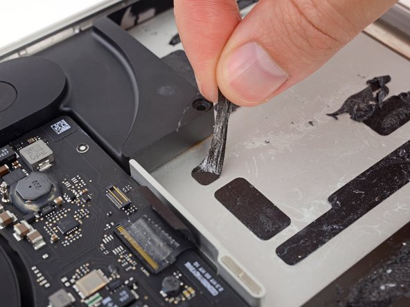
Usa il pollice o le dita per tenere piegata la barra a molla in plastica sul vassoio dell'SSD, liberando le due clip sul lato frontale del dispositivo.
-
Mentre tieni premuta la barra a molla, fai ruotare verso l'alto, fuori dalla sua cavità, il gruppo SSD.
-
-
-
Rimuovi le tre viti Torx T5 da 2,2 mm presenti su ogni lato della batteria (sei viti in totale).
-
-
-
-
Ora che il tuo MacBook Pro è stato preparato per l'intervento, è ora di preparare anche te.
-
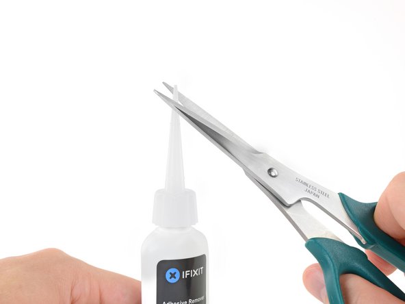
Indossa occhiali protettivi quando maneggi e applichi l'antiadesivo (gli occhiali protettivi sono inclusi nel tuo kit).
-
Non indossare lenti a contatto senza gli occhiali protettivi.
-
Anche i guanti protettivi sono inclusi nel tuo kit. Se ti preoccupa un'eventuale irritazione alla pelle, mettiti subito i guanti.
-
-
-
Ripeti i passi precedenti per separare la cella adiacente dal suo adesivo:
-
Applica poche gocce di antiadesivo sotto la cella della batteria.
-
Attendi 2-3 minuti per lasciar penetrare l'antiadesivo e ammorbidire la colla.
-
Incunea con delicatezza, verso l'interno, uno spudger o una scheda di plastica, stando attento non danneggiare la batteria e separa la cella della batteria dall'adesivo che la fissa al tuo MacBook Pro.
-
-
-
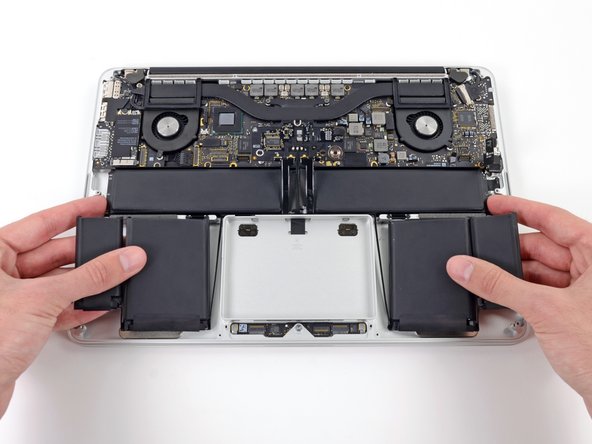
Solleva in una volta sola l'intera batteria fuori dal case superiore e rimuovila.
-
Con un po' di fortuna, dovresti riuscire un po' alla volta a staccare ogni striscia di adesivo con le dita.
-
In caso contrario, bagna ogni striscia di adesivo con un po' di antiadesivo per 2-3 minuti e poi grattala via con uno strumento di plastica. Può essere richiesto abbastanza lavoro, quindi cerca di avere pazienza.
-
Elimina ogni traccia dell'adesivo rimanente e lascia asciugare all'aria il tuo MacBook Pro per qualche minuto.
-
Calibra la nuova batteria appena installata: carica al 100% e tieni in carica almeno altre 2 ore. Stacca il cavo e usa il laptop per farlo scaricare. All'avviso di batteria in esaurimento, salva il lavoro corrente e tieni acceso il MacBook finché non si iberna perché scarico. Aspetta almeno altre 5 ore, poi carica senza interruzioni fino al 100%.
-
-
Questo passaggio è privo di traduzione. Aiuta a tradurlo
-
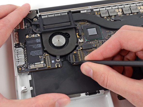
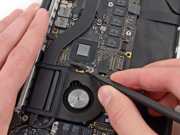
Use the tip of a spudger to push the edges of the I/O board connector straight out of its socket on the logic board.
-
-
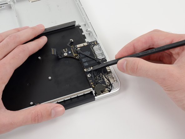
Questo passaggio è privo di traduzione. Aiuta a tradurlo
-
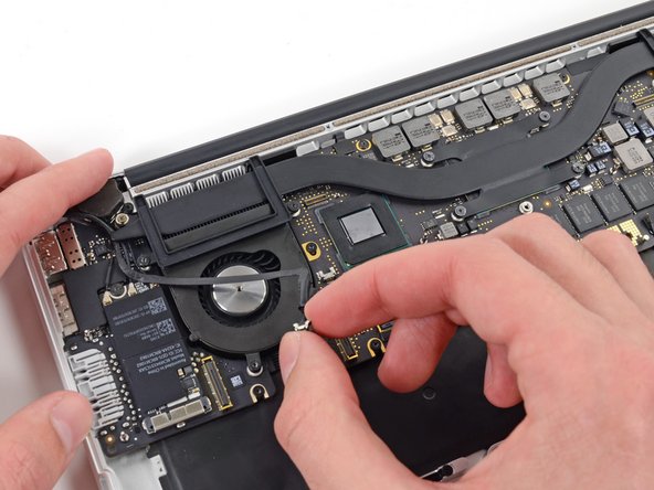
Use the tip of a spudger to push the iSight camera cable connector straight away from its socket on the logic board.
-
-
Questo passaggio è privo di traduzione. Aiuta a tradurlo
-
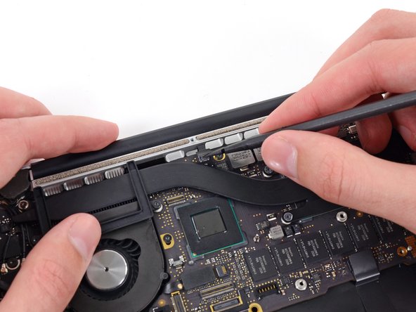
Wedge the flat end of a spudger underneath the keyboard backlight connector and the logic board.
-
Gently twist the flat end of a spudger upwards to pry the keyboard backlight connector up off its socket on the logic board.
-
-
Questo passaggio è privo di traduzione. Aiuta a tradurlo
-
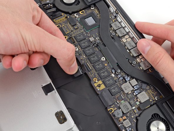
Use the tip of a spudger to flip up the retaining flap on the trackpad ribbon cable ZIF socket.
-
Grasp the plastic pull tab and pull the trackpad ribbon cable out of its socket.
-
-
Questo passaggio è privo di traduzione. Aiuta a tradurlo
-
Use the tip of a spudger to flip up the retaining flap on the keyboard ribbon cable ZIF socket.
-
Grasp the plastic pull tab and pull the keyboard ribbon cable out of its socket.
-
-
Questo passaggio è privo di traduzione. Aiuta a tradurlo
-
Use the tip of a spudger to flip up the retaining flap on the microphone ribbon cable ZIF socket.
-
Grasp the plastic pull tab and pull the microphone ribbon cable out of its socket.
-
-
Questo passaggio è privo di traduzione. Aiuta a tradurlo
-
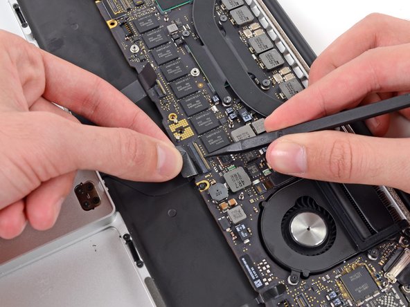
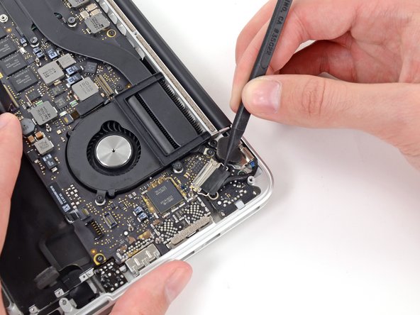
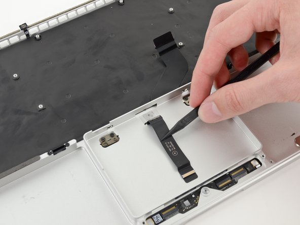
Use the tip of a spudger to rotate the pull tab secured to the display data cable lock toward the DC-In side of the computer.
-
-
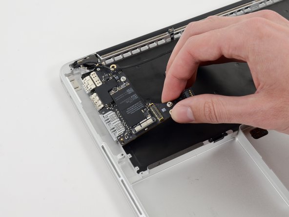
Questo passaggio è privo di traduzione. Aiuta a tradurlo
-
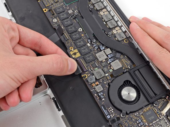
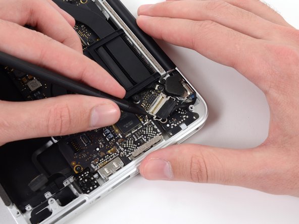
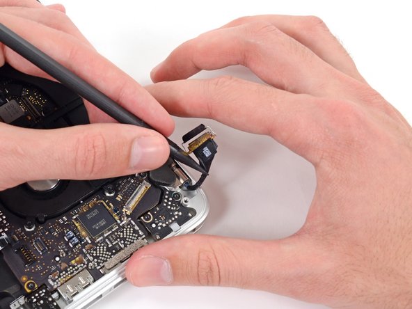
Gently push the edges of the display data cable connector away from its socket on the logic board.
-
Pull, but do not remove, the display data cable connector out of its socket and carefully move it out of the way.
-
-
Questo passaggio è privo di traduzione. Aiuta a tradurlo
-
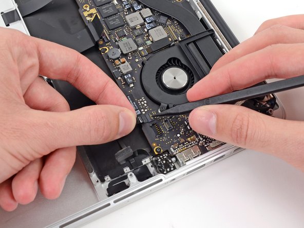
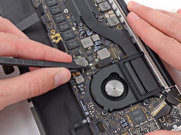
Use the tip of a spudger to flip up the retaining flap on the left fan ribbon cable ZIF socket.
-
Carefully pull the left fan ribbon cable out of its socket.
-
-
Questo passaggio è privo di traduzione. Aiuta a tradurlo
-
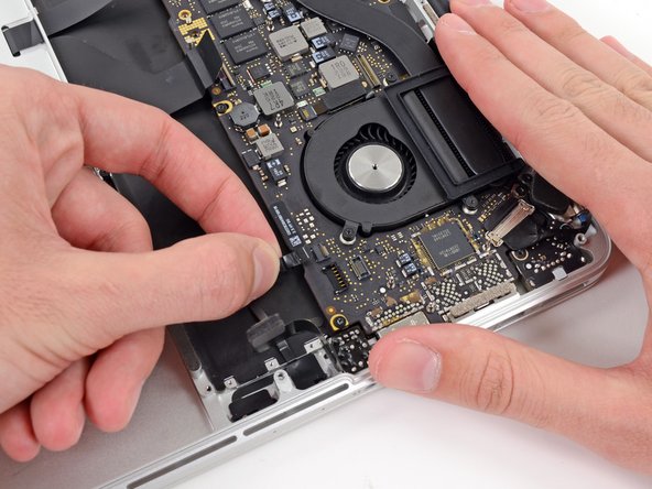
Move the left fan ribbon cable aside to reveal a hidden screw securing the logic board assembly to the upper case.
-
-
Questo passaggio è privo di traduzione. Aiuta a tradurlo
-
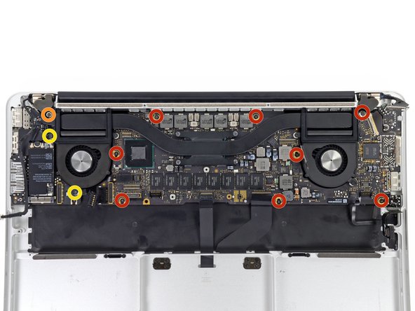
Remove the following screws securing the logic board to the upper case:
-
Eight 3.3 mm T5 Torx screws
-
One Phillips #00 screw
-
Two 3.1 mm T5 Torx screws
-
Remove two more screws, from the MagSafe DC-In board in the upper right corner (second image).
-
Two 3.4 mm T5 Torx screws
-
-
Questo passaggio è privo di traduzione. Aiuta a tradurlo
-
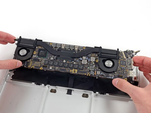
Carefully lift the logic board assembly from its left side and work it out of the upper case, minding any cables and the I/O ports that may get caught during removal.
-
Pull the right I/O port side of the logic board away from the side of the upper case and remove the logic board assembly.
-
-
Questo passaggio è privo di traduzione. Aiuta a tradurlo
-
Use the flat end of a spudger to pry and disconnect the three antenna cable connectors from the AirPort board.
-
Connect the long-sleeved cable to the center socket.
-
The short-sleeved cable connects next to the screw.
-
The remaining cable has no sleeve, and connects in the last empty socket, next to the fan.
-
-
Questo passaggio è privo di traduzione. Aiuta a tradurlo
-
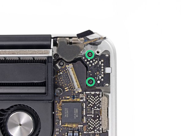
Remove the following two screws securing the I/O board to the upper case:
-
One 3.53 mm T5 Torx screw
-
One 4.89 mm T8 Torx standoff screw
-
-
Questo passaggio è privo di traduzione. Aiuta a tradurlo
-
Carefully pull and remove the I/O board away from its recess in the upper case.
-
-
Questo passaggio è privo di traduzione. Aiuta a tradurlo
-
Remove the two 3.4 mm T5 Torx screws securing the headphone jack to the upper case.
-
-
Questo passaggio è privo di traduzione. Aiuta a tradurlo
-
Lift and remove the headphone jack out of the upper case.
-
-
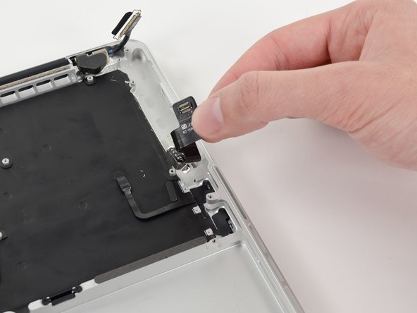
Questo passaggio è privo di traduzione. Aiuta a tradurlo
-
Use a pair of tweezers to lift the rubber hinge covers up off the right and left display hinges.
-
-
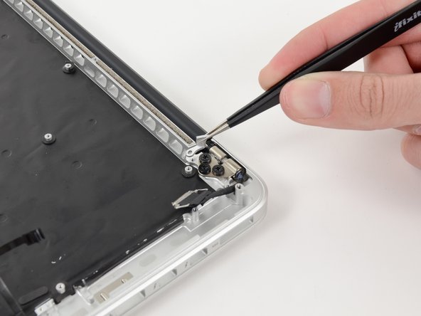
Questo passaggio è privo di traduzione. Aiuta a tradurlo
-
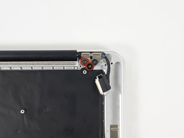
Remove the 3.2 mm T5 Torx screws (one on each side) securing the aluminum hinge brackets to the upper case.
-
-
Questo passaggio è privo di traduzione. Aiuta a tradurlo
-
Use a pair of tweezers to lift aluminum hinge brackets off the right and left display hinges.
-
-
Questo passaggio è privo di traduzione. Aiuta a tradurlo
-
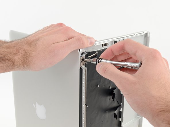
Remove the four inner 5.3 mm T8 Torx screws (two on each side) securing the display to the upper case.
-
-
Questo passaggio è privo di traduzione. Aiuta a tradurlo
-
While holding the display and upper case together with your left hand, remove the remaining T8 Torx screw from the lower display bracket.
-
Remove the last remaining T8 Torx screw securing the display to the upper case.
-
-
Questo passaggio è privo di traduzione. Aiuta a tradurlo
-
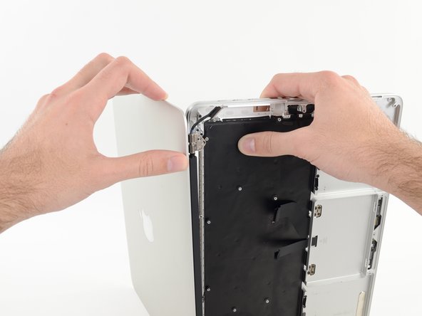
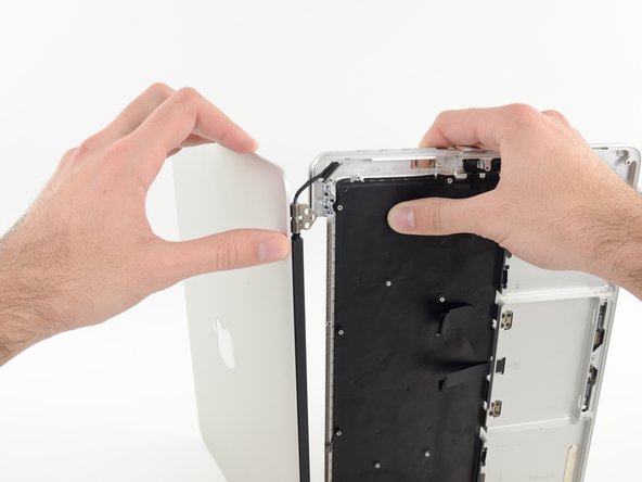
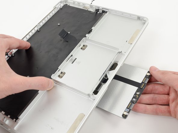
Grip both halves of the device, one in each hand.
-
Gently push forward on the bottom half of the device to detach it from the display assembly.
-
Carefully set each component aside, making sure to set down the lower half keyboard-side down.
-
-
Questo passaggio è privo di traduzione. Aiuta a tradurlo
-
Remove the following screws securing the trackpad to the upper case:
-
Four 1.4 mm Phillips #000 screws
-
-
Questo passaggio è privo di traduzione. Aiuta a tradurlo
-
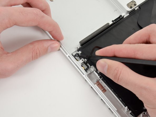
Wedge the spudger between the trackpad ribbon cable and the upper case.
-
Run the spudger along the bottom to release the trackpad ribbon cable from the adhesive securing it to the upper case.
-
-
Questo passaggio è privo di traduzione. Aiuta a tradurlo
-
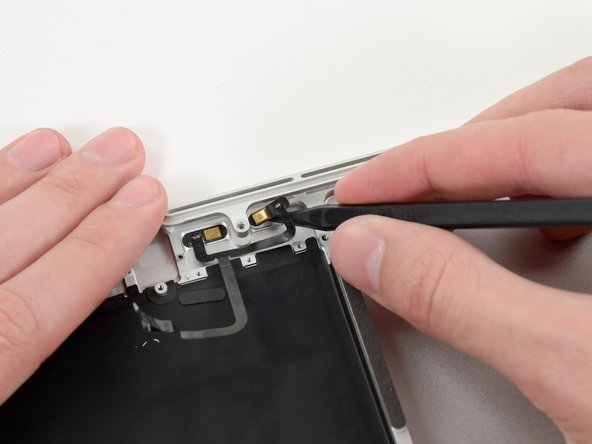
Insert the tip of a spudger in between the trackpad ribbon cable and the upper case.
-
Carefully thread the trackpad ribbon cable out of the notch near the top of the SSD assembly cavity.
-
-
Questo passaggio è privo di traduzione. Aiuta a tradurlo
-
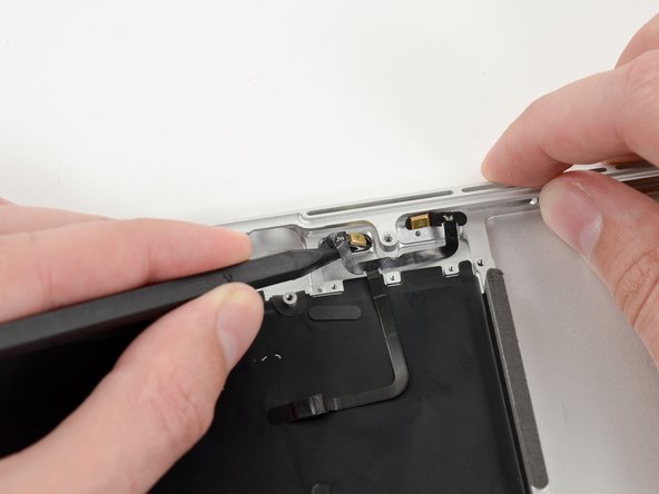
Once the trackpad is free of the upper case, guide the trackpad ribbon cable through the slot cut in the upper case.
-
Remove the trackpad from the upper case.
-
-
Questo passaggio è privo di traduzione. Aiuta a tradurlo
-
For this step, it is recommended to use a heat gun or hair dryer to soften the adhesive securing the microphone assembly to the upper case. You may be able to remove it without doing so, but will risk damaging the microphone cable.
-
With the heat gun set to low, heat the microphone assembly to loosen the adhesive attaching it to the upper case.
-
-
Questo passaggio è privo di traduzione. Aiuta a tradurlo
-
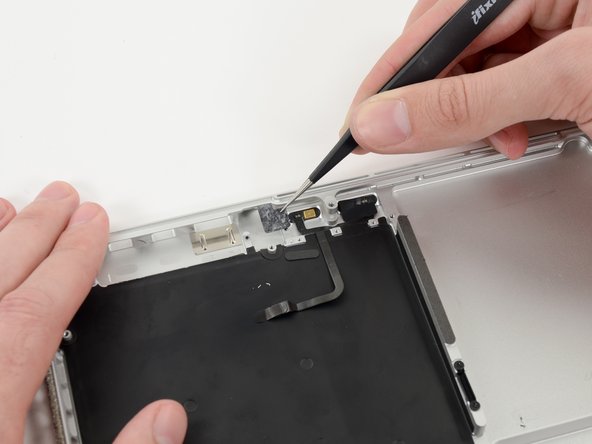
Use the tip of a spudger to remove the piece of tape covering one of two microphones.
-
Grasp the piece of tape with a pair of tweezers and remove it.
-
-
Questo passaggio è privo di traduzione. Aiuta a tradurlo
-
Repeat the same procedure as the previous step to remove the tape covering the second microphone.
-
-
Questo passaggio è privo di traduzione. Aiuta a tradurlo
-
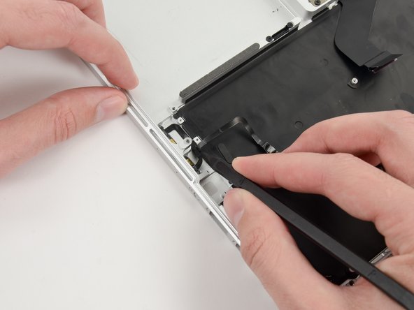
Wedge the tip of a spudger underneath the microphone assembly cable.
-
Run the spudger up along the bottom of the microphone assembly cable to separate it from the upper case.
-
-
Questo passaggio è privo di traduzione. Aiuta a tradurlo
-
Gently wedge the tip of a spudger underneath the second microphone and push inwards to loosen the adhesive.
-
-
Questo passaggio è privo di traduzione. Aiuta a tradurlo
-
Carefully pry the first microphone up off the upper case.
-
-
Questo passaggio è privo di traduzione. Aiuta a tradurlo
-
Lift and remove the microphone assembly out of the upper case.
-


Annulla: non ho completato questa guida.
Altre 7 persone hanno completato questa guida.

