Questa versione può contenere modifiche errate. Passa all'ultima istantanea verificata.
Cosa ti serve
-
-
Rimuovi le 10 viti seguenti che fissano il coperchio inferiore al case superiore:
-
Due viti Pentalobe da 2,3 mm
-
Otto viti Pentalobe da 3,0 mm
-
-
-
Rimuovi la copertura in plastica attaccata alla scheda dei contatti della batteria.
-
-
-
Afferra con delle pinzette l'interposer.
-
Solleval'interposer dalla scheda logica e rimuovilo.
-
-
-
Questo passaggio è privo di traduzione. Aiuta a tradurlo
-
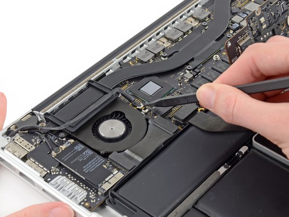
Use the tip of a spudger to push the iSight camera cable connector straight away from its socket on the logic board.
-
-
Questo passaggio è privo di traduzione. Aiuta a tradurlo
-
Use the flat end of a spudger to pry and disconnect the three antenna cable connectors from the AirPort board.
-
The three cables are coded with black sleeves of different lengths. During reassembly:
-
Connect the long-sleeved cable to the socket closest to the ports.
-
The short-sleeved cable connects next to the screw.
-
The remaining cable has no sleeve, and connects in the last empty socket, next to the fan.
-
-
Questo passaggio è privo di traduzione. Aiuta a tradurlo
-
Move the antenna cables aside, clear of the AirPort board.
-
-
Questo passaggio è privo di traduzione. Aiuta a tradurlo
-
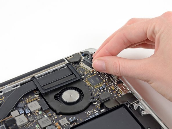
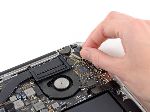
Grab the black pull tab secured to the display data cable lock and rotate it toward the DC-In side of the computer.
-
Pull the display data cable straight out of its socket on the logic board.
-
-
Questo passaggio è privo di traduzione. Aiuta a tradurlo
-
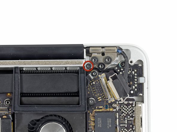
Use a pair of tweezers to lift the rubber hinge covers up off the right and left display hinges.
-
-
Questo passaggio è privo di traduzione. Aiuta a tradurlo
-
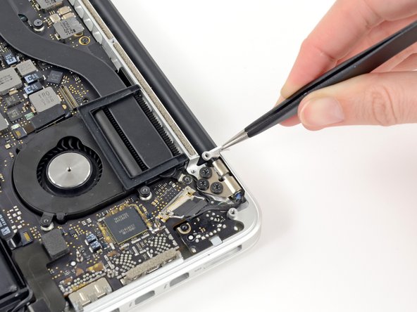
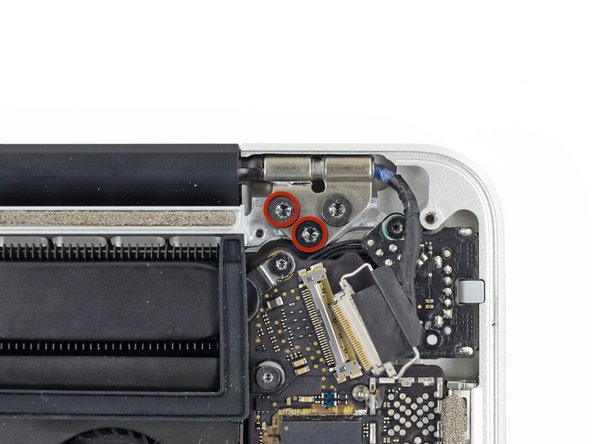
Remove the two 3.1 mm T5 Torx screws securing the aluminum hinge brackets.
-
-
Questo passaggio è privo di traduzione. Aiuta a tradurlo
-
Use a pair of tweezers to lift aluminum hinge brackets off the right and left display hinges.
-
-
Questo passaggio è privo di traduzione. Aiuta a tradurlo
-
Remove the four inner 5.3 mm T8 Torx screws (two on each side) securing the display to the upper case.
-
-
Questo passaggio è privo di traduzione. Aiuta a tradurlo
-
While holding the display and upper case together with your left hand, remove the remaining T8 Torx screw from the upper display bracket.
-
Remove the last remaining T8 Torx screw securing the display to the upper case.
-
-
Questo passaggio è privo di traduzione. Aiuta a tradurlo
-
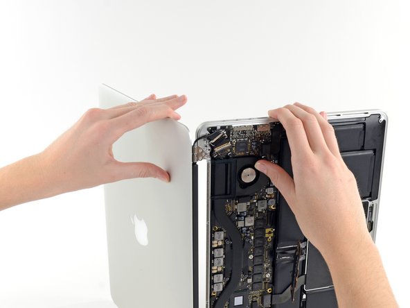
Grip both halves of the device, one in each hand.
-
Gently push forward on the bottom half of the device to detach it from the display assembly.
-
Carefully set each component aside, making sure to set down the lower half keyboard-side down.
-
-
Questo passaggio è privo di traduzione. Aiuta a tradurlo
-
With the display facing towards you and the plastic clutch cover down, grab the clutch cover and slide it all the way to the right, towards the hinge.
-
Lift the plastic cover from the bottom and remove it from the display.
-
-
Questo passaggio è privo di traduzione. Aiuta a tradurlo
-
Peel up the tape covering the cable connector.
-
-
Questo passaggio è privo di traduzione. Aiuta a tradurlo
-
Remove the two screws securing the cable to the case:
-
Two T8 Torx screws.
-
-
Questo passaggio è privo di traduzione. Aiuta a tradurlo
-
Remove the six screws securing the antenna assembly in place:
-
Six PH00 Phillips screws.
-
Lift the antenna assembly to reveal the LCD cable connector underneath the left side.
-
-
Questo passaggio è privo di traduzione. Aiuta a tradurlo
-
Grab the metal bar securing the LCD cable connector in place and rotate it towards the bottom of the display.
-
Pull the LCD cable straight out of its socket on the display.
-


Annulla: non ho completato questa guida.
Altre 17 persone hanno completato questa guida.

Team

6 Commenti
Hi,
Can anyone help me ? It might be possible that my MacBook Pro 13” early 2015 restarts by it self once in a few minutes because this cable is slightly damaged? It had before LCD problems and has been serviced. As I have noticed, when I touch the cable and move it a little bit, computer restarts immediately, so I thought this might be the restarting problem.
(I have to say that I have already tried other options : I have fresh reinstalled the operating system, so theres no software issue, I have repasted the processor, I have checked the cables connections). The only strange thing is that it doesn’t turn on with the battery disconnected…
Does anyone have any suggestion?
Thanks a lot!!
Are there instructions using the MacBook Pro (Retina, 15-inch, Early 2013)? The inside is completely different. Alas.
I'm getting this because the hing broke. The real problem is both hinges have broken. Seems like the other hinge is not possible to replace. Is that right? Will just this one side be enough to open with light use? My Mac is a early 2013 15inch pro. Model A1398
This works on a mid-2015 Pro Retina also. The display is *slightly* different in that the black antenna cover does not simply slide to one side and come off. It has little tiny end caps that can be popped on/off. Apart from that and the antenna had one more screw all the way on the right (away from the display connecter) that doesn’t have to be removed to just lift up the antenna and while holding the antenna slightly up, you can remove and replace the LCD connector. All else was the same and I was able to fix my Mid 2015 MacBook Retina Pro. Thanks iFixit!!!
Hey peeps, hope you are all doing well
I have a backlight issue with my MacBook Pro early 2013 Retina display 13 in and I am trying to figure out where the issue is stemming from. I am wondering if i could use the LCD cable from an older model (Unibody mid 2010 matchbook pro 13in), would that work or be compatible with my current device? Any insight would be highly appreciated, Thank you.