Questa versione può contenere modifiche errate. Passa all'ultima istantanea verificata.
Cosa ti serve
-
CompraAttrezzo utilizzato in questo passaggio:P5 Pentalobe Screwdriver Retina MacBook Pro and Air$5.99
-
Rimuovi le seguenti dieci viti:
-
Due viti a cinque punte Pentalobe da 9 mm
-
Otto viti a cinque punte Pentalobe da 2,6 mm
-
-
Questo passaggio è privo di traduzione. Aiuta a tradurlo
-
Grab the clear plastic pull tab attached to the battery connector and pull it toward the front edge of the Air to disconnect the battery from the logic board.
-
-
Questo passaggio è privo di traduzione. Aiuta a tradurlo
-
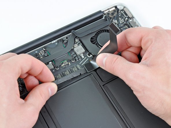
Use the flat end of a spudger to pry the I/O board cable connector upward out of its socket on the I/O board.
-
-
Questo passaggio è privo di traduzione. Aiuta a tradurlo
-
Carefully peel the I/O board cable from the top of the fan.
-
While gently pulling the I/O board cable upward near its connection to the logic board, use the tip of a spudger to pry upward on alternating sides of the connector to help "walk" it out of its socket.
-
Remove the I/O board cable.
-
-
Questo passaggio è privo di traduzione. Aiuta a tradurlo
-
Use the tip of a spudger to carefully flip up the retaining flap on the fan cable ZIF socket.
-
-
Questo passaggio è privo di traduzione. Aiuta a tradurlo
-
Peel the rubber gasket off the adhesive on the top of the fan.
-
-
Questo passaggio è privo di traduzione. Aiuta a tradurlo
-
Remove the following three screws securing the fan to the upper case:
-
One 3.6 mm T5 Torx screw
-
One 2.7 mm T5 Torx screw
-
One 3.6 mm T5 Torx screw with a short head
-
-
Questo passaggio è privo di traduzione. Aiuta a tradurlo
-
Lift the fan out of the upper case and carefully pull the fan ribbon cable out of its socket as you remove it from the Air.
-
-
Questo passaggio è privo di traduzione. Aiuta a tradurlo
-
Disconnect the I/O board by pulling the power cable away from its socket on the logic board.
-
-
Questo passaggio è privo di traduzione. Aiuta a tradurlo
-
Pull the camera cable parallel to the face of the I/O board toward the corner of the Air to disconnect it from its socket, using the tip of a spudger to help push the connector out of its socket.
-
-
Questo passaggio è privo di traduzione. Aiuta a tradurlo
-
Use the flat end of a spudger to pry the left speaker cable connector up and out of its socket on the I/O board.
-
De-route the left speaker cable from its retainer on the I/O board.
-
-
-
Questo passaggio è privo di traduzione. Aiuta a tradurlo
-
Use the flat end of a spudger to pry the microphone cable connector up and out of its socket on the I/O board.
-
-
Questo passaggio è privo di traduzione. Aiuta a tradurlo
-
Remove the single 3.6 mm T5 Torx screw securing the I/O board to the upper case.
-
-
Questo passaggio è privo di traduzione. Aiuta a tradurlo
-
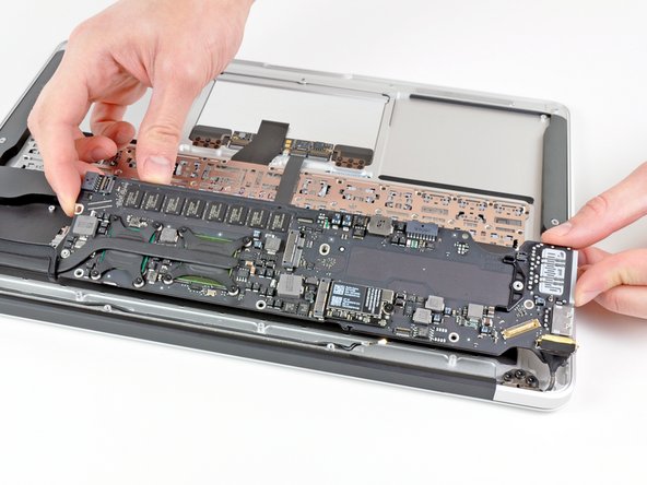
Carefully lift the I/O board from its edge nearest the logic board and remove it from the upper case.
-
-
Questo passaggio è privo di traduzione. Aiuta a tradurlo
-
Remove the following five screws securing the battery to the upper case:
-
Three 6.3 mm T5 Torx screws
-
Two 2.4 mm T5 Torx screws
-
-
Questo passaggio è privo di traduzione. Aiuta a tradurlo
-
Lift the battery from its edge nearest the logic board and remove it from the upper case.
-
-
Questo passaggio è privo di traduzione. Aiuta a tradurlo
-
Use the tip of a spudger or your fingernail to flip up the retaining flap on the trackpad ribbon cable ZIF socket.
-
Pull the trackpad ribbon cable straight out of its socket toward the front edge of the Air.
-
-
Questo passaggio è privo di traduzione. Aiuta a tradurlo
-
Use the flat end of a spudger to pry the right speaker cable connector up and out of its socket on the logic board.
-
-
Questo passaggio è privo di traduzione. Aiuta a tradurlo
-
Gently push the tip of a spudger under the black plastic flap stuck to the display data cable lock to make the lock pop upward and away from the socket.
-
While holding the lock away from the socket, use the tip of a spudger and your fingers to gently remove the display data cable from its socket by sliding it toward the corner of the Air.
-
-
Questo passaggio è privo di traduzione. Aiuta a tradurlo
-
Use the flat end of a spudger to pry both antenna cable connectors up and off their sockets on the AirPort/Bluetooth card.
-
-
Questo passaggio è privo di traduzione. Aiuta a tradurlo
-
Gently de-route the antenna cables from the slot cut into the logic board.
-
-
Questo passaggio è privo di traduzione. Aiuta a tradurlo
-
Remove the single 2.85 mm T5 Torx screw securing the SSD to the logic board.
-
-
Questo passaggio è privo di traduzione. Aiuta a tradurlo
-
Pull the drive straight out of its socket and remove it from the logic board.
-
-
Questo passaggio è privo di traduzione. Aiuta a tradurlo
-
Remove the six 6.3 mm T5 Torx screws securing the logic board to the upper case.
-
-
Questo passaggio è privo di traduzione. Aiuta a tradurlo
-
Remove the inner two 4.9 mm T8 Torx screws securing the antenna cable retainer and left clutch hinge to the upper case.
-
-
Questo passaggio è privo di traduzione. Aiuta a tradurlo
-
Push the antenna cable retainer away slightly and remove the 3 mm T5 Torx screw securing the end of the heat sink to the upper case.
-
-
Questo passaggio è privo di traduzione. Aiuta a tradurlo
-
Carefully remove the logic board assembly from the upper case, minding any cables that may get caught.
-
-
Questo passaggio è privo di traduzione. Aiuta a tradurlo
-
Remove the single 2.9 mm T5 Torx screw securing the AirPort/Bluetooth card to the logic board.
-
-
Questo passaggio è privo di traduzione. Aiuta a tradurlo
-
Slightly lift the free end of the AirPort/Bluetooth board and pull it out of its socket on the logic board.
-
Remove the AirPort/Bluetooth board from the logic board.
-
-
Questo passaggio è privo di traduzione. Aiuta a tradurlo
-
Remove the eight 2.5 mm T5 Torx screws securing the heat sink to the logic board.
-
-
Questo passaggio è privo di traduzione. Aiuta a tradurlo
-
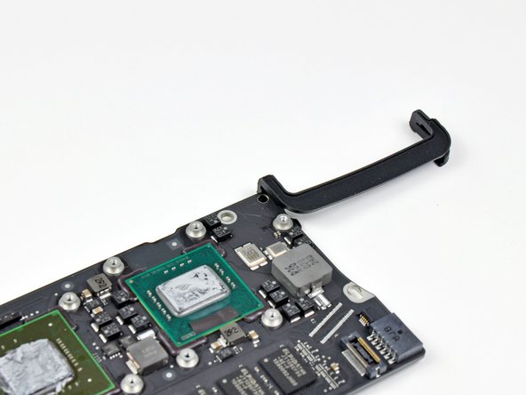
Remove the heat sink from the logic board.
-
When reinstalling the heat sink, be sure to apply a new layer of thermal paste. If you have never applied thermal paste before, we have a guide that makes it easy.
-
-
Questo passaggio è privo di traduzione. Aiuta a tradurlo
-
Remove the rubber fan gasket from the logic board.
-
Logic board remains.
-


Annulla: non ho completato questa guida.
Altre 33 persone hanno completato questa guida.

4 Commenti
Can I use a later model logic board in the 2010 model?
Later models logic board have connection for backlit keyboard next to battery connector. Also different shaped right speaker
Please be so nice and let me know if logic board replacement at my late 2010 with 2G RAM in to the same model but with 4G RAM, will give me visible, tangible nice results, that the speed is improved ? It should but can someone confirm it ?
Hi Artur,
TL;DR: Yes!
If you have a look in the “activity monitor” unter memory, you will find that with just 2GB of RAM, OS X will almost always use some “Swap” memory, which means, it has to offload files from the RAM to the HDD (SDD). Whenever this happens, the system will get a lot less responsive, since moving files from the RAM to the SSD and back is a lot slower, than just reading/writing from/to the RAM. In my experience, with 2GB this happens all the time, whereas with 4GB, you have to run a number of programs at once, until that happens.
To be clear: 4GB will not suddenly make this a fast machine, it’s still a 10+ years als Core2Duo, but it will be a lot more responsive and usable with 4GB in it. The replacement process is relatively easy, as you can see in the guide, as long as you got the right screwdrivers. If you can get a 4 GB board for a decent price, give it a try!
NebukadV -