Questa versione può contenere modifiche errate. Passa all'ultima istantanea verificata.
Cosa ti serve
-
CompraAttrezzo utilizzato in questo passaggio:P5 Pentalobe Screwdriver Retina MacBook Pro and Air$5.99
-
Rimuovi le seguenti dieci viti:
-
Due viti a cinque punte Pentalobe da 9 mm
-
Otto viti a cinque punte Pentalobe da 2,6 mm
-
-
Questo passaggio è privo di traduzione. Aiuta a tradurlo
-
Grab the clear plastic pull tab attached to the battery connector and pull it toward the front edge of the Air to disconnect the battery from the logic board.
-
-
Questo passaggio è privo di traduzione. Aiuta a tradurlo
-
Use the flat end of a spudger to pry the I/O board cable connector upward out of its socket on the I/O board.
-
-
Questo passaggio è privo di traduzione. Aiuta a tradurlo
-
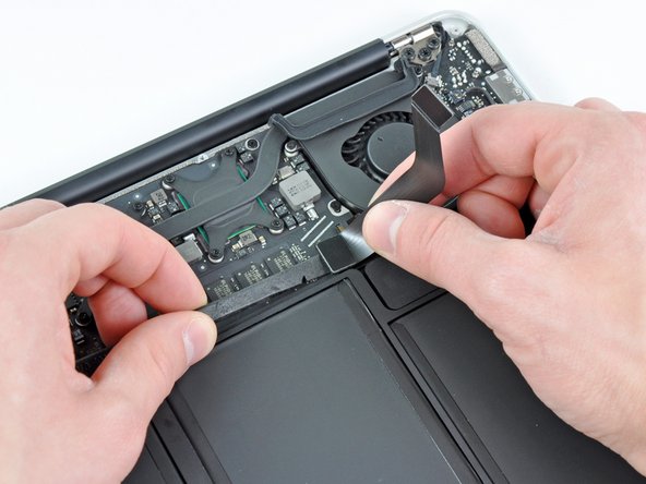
Carefully peel the I/O board cable from the top of the fan.
-
While gently pulling the I/O board cable upward near its connection to the logic board, use the tip of a spudger to pry upward on alternating sides of the connector to help "walk" it out of its socket.
-
Remove the I/O board cable.
-
-
Questo passaggio è privo di traduzione. Aiuta a tradurlo
-
Use the tip of a spudger to carefully flip up the retaining flap on the fan cable ZIF socket.
-
-
Questo passaggio è privo di traduzione. Aiuta a tradurlo
-
Peel the rubber gasket off the adhesive on the top of the fan.
-
-
-
Questo passaggio è privo di traduzione. Aiuta a tradurlo
-
Remove the following three screws securing the fan to the upper case:
-
One 3.6 mm T5 Torx screw
-
One 2.7 mm T5 Torx screw
-
One 3.6 mm T5 Torx screw with a short head
-
-
Questo passaggio è privo di traduzione. Aiuta a tradurlo
-
Lift the fan out of the upper case and carefully pull the fan ribbon cable out of its socket as you remove it from the Air.
-
-
Questo passaggio è privo di traduzione. Aiuta a tradurlo
-
Disconnect the I/O board by pulling the power cable away from its socket on the logic board.
-
-
Questo passaggio è privo di traduzione. Aiuta a tradurlo
-
Pull the camera cable parallel to the face of the I/O board toward the corner of the Air to disconnect it from its socket, using the tip of a spudger to help push the connector out of its socket.
-
-
Questo passaggio è privo di traduzione. Aiuta a tradurlo
-
Use the flat end of a spudger to pry the left speaker cable connector up and out of its socket on the I/O board.
-
De-route the left speaker cable from its retainer on the I/O board.
-
-
Questo passaggio è privo di traduzione. Aiuta a tradurlo
-
Use the flat end of a spudger to pry the microphone cable connector up and out of its socket on the I/O board.
-
-
Questo passaggio è privo di traduzione. Aiuta a tradurlo
-
Remove the single 3.6 mm T5 Torx screw securing the I/O board to the upper case.
-
-
Questo passaggio è privo di traduzione. Aiuta a tradurlo
-
Carefully lift the I/O board from its edge nearest the logic board and remove it from the upper case.
-
-
Questo passaggio è privo di traduzione. Aiuta a tradurlo
-
Remove the eight 2.5 mm T5 Torx screws securing the heat sink to the logic board.
-
-
Questo passaggio è privo di traduzione. Aiuta a tradurlo
-
Remove the two 4.9 mm T8 Torx screw securing the antenna cable retainer on the left display hinge to the upper case.
-
-
Questo passaggio è privo di traduzione. Aiuta a tradurlo
-
Push the antenna cable retainer out of the way and remove the 3 mm T5 Torx screw securing the end of the heat sink to the upper case.
-
-
Questo passaggio è privo di traduzione. Aiuta a tradurlo
-
Remove the heat sink from the logic board.
-
When reinstalling the heat sink, be sure to apply a new layer of thermal paste. If you have never applied thermal paste before, we have a guide that makes it easy.
-


Annulla: non ho completato questa guida.
Altre 7 persone hanno completato questa guida.
