Questa versione può contenere modifiche errate. Passa all'ultima istantanea verificata.
Cosa ti serve
-
CompraAttrezzo utilizzato in questo passaggio:P5 Pentalobe Screwdriver Retina MacBook Pro and Air$5.99
-
Svita le seguenti dieci viti:
-
Due viti pentalobe da 8 mm
-
Otto viti pentalobe da 2,5 mm
-
-
Questo passaggio è privo di traduzione. Aiuta a tradurlo
-
Use the flat end of a spudger to pry both short sides of the battery connector upward to disconnect it from its socket on the logic board.
-
Bend the battery cable slightly away from the logic board so the connector will not accidentally contact its socket.
-
-
Questo passaggio è privo di traduzione. Aiuta a tradurlo
-
Remove the single 2.9 mm T5 Torx screw securing the SSD to the logic board.
-
-
Questo passaggio è privo di traduzione. Aiuta a tradurlo
-
Use a spudger to help lift the free end of the SSD just enough to grab it with your other hand.
-
Pull the drive straight out of its socket and remove it from the logic board.
-
-
Questo passaggio è privo di traduzione. Aiuta a tradurlo
-
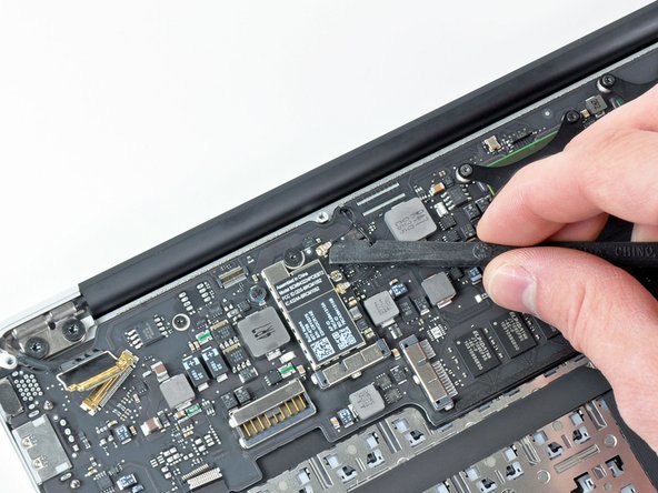
Use the flat end of a spudger to pry the I/O board cable connector upward out of its socket on the I/O board.
-
-
Questo passaggio è privo di traduzione. Aiuta a tradurlo
-
While gently pulling the I/O board cable upward near its connection to the logic board, use the tip of a spudger to pry upward on alternating sides of the connector to help "walk" it out of its socket.
-
Remove the I/O board cable.
-
-
Questo passaggio è privo di traduzione. Aiuta a tradurlo
-
Use the tip of a spudger to carefully flip up the retaining flap on the fan cable ZIF socket.
-
-
Questo passaggio è privo di traduzione. Aiuta a tradurlo
-
Remove the following three screws securing the fan to the upper case:
-
Two 5.2 mm T5 Torx screws
-
One 3.6 mm T5 Torx screw
-
-
-
Questo passaggio è privo di traduzione. Aiuta a tradurlo
-
Lift the fan out of the upper case and carefully pull the fan ribbon cable out of its socket as you remove it from the Air.
-
-
Questo passaggio è privo di traduzione. Aiuta a tradurlo
-
Remove the following five screws securing the battery to the upper case:
-
Two 5.2 mm T5 Torx screws
-
One 6 mm T5 Torx screw
-
Two 2.6 mm T5 Torx screws
-
-
Questo passaggio è privo di traduzione. Aiuta a tradurlo
-
Lift the battery from its edge nearest the logic board and remove it from the upper case.
-
-
Questo passaggio è privo di traduzione. Aiuta a tradurlo
-
Disconnect the I/O board by pulling the power cable away from its socket on the logic board.
-
-
Questo passaggio è privo di traduzione. Aiuta a tradurlo
-
Use the tip of a spudger or your fingernail to flip up the retaining flap on the trackpad ribbon cable ZIF socket.
-
Pull the trackpad ribbon cable straight out of its socket toward the front edge of the Air.
-
-
Questo passaggio è privo di traduzione. Aiuta a tradurlo
-
Use the tip of a spudger to de-route the right speaker cable from the slot cut into the logic board.
-
-
Questo passaggio è privo di traduzione. Aiuta a tradurlo
-
Use the flat end of a spudger to pry the right speaker cable connector up and out of its socket on the logic board.
-
-
Questo passaggio è privo di traduzione. Aiuta a tradurlo
-
Gently push the tip of a spudger under the black plastic flap stuck to the display data cable lock to make the lock pop upward and away from the socket.
-
While holding the lock away from the socket, use the tip of a spudger and your fingers to gently remove the display data cable from its socket.
-
-
Questo passaggio è privo di traduzione. Aiuta a tradurlo
-
Remove the small rubber gasket from the corner of the upper case near the display data cable.
-
-
Questo passaggio è privo di traduzione. Aiuta a tradurlo
-
Use the flat end of a spudger to pry both antenna cable connectors up and off their sockets on the AirPort/Bluetooth card.
-
-
Questo passaggio è privo di traduzione. Aiuta a tradurlo
-
Gently de-route the antenna cables from the slot cut into the logic board.
-
-
Questo passaggio è privo di traduzione. Aiuta a tradurlo
-
Remove the three 3.6 mm T5 Torx screws securing the logic board to the upper case.
-
-
Questo passaggio è privo di traduzione. Aiuta a tradurlo
-
Gently lift the logic board assembly out of the upper case, minding the fragile heat sink and any cables that may get caught.
-
-
Questo passaggio è privo di traduzione. Aiuta a tradurlo
-
Remove the single 2.9 mm T5 Torx screw securing the AirPort/Bluetooth card to the logic board.
-
-
Questo passaggio è privo di traduzione. Aiuta a tradurlo
-
Slightly lift the free end of the AirPort/Bluetooth board and pull it out of its socket on the logic board.
-
Remove the AirPort/Bluetooth board from the logic board.
-
-
Questo passaggio è privo di traduzione. Aiuta a tradurlo
-
Remove the eight 2.5 mm T5 Torx screws securing the heat sink to the logic board.
-
-
Questo passaggio è privo di traduzione. Aiuta a tradurlo
-
Remove the heat sink from the logic board.
-
Logic board remains.
-
When reinstalling the heat sink, be sure to apply a new layer of thermal paste. If you have never applied thermal paste before, we have a guide that makes it easy.
-


Annulla: non ho completato questa guida.
Altre 23 persone hanno completato questa guida.

7 Commenti
Just so you guys know I could successfully reaplace the A1370 Core2Duo Late 2010 board for a A1370 i7 Mid 2011 board. you are going to need the heatsink and battery from the newer model as well. the problem I am facing right now is the wifi/bluetooth antenna been too short for the new position of the airport card. as soon as I get a chance I'll try to re route the cables and try to fix it.
Igorfeghali, another question: why do you need the battery too?
kautame -
Hello everybody,
I made it too: I replaced my 2GB RAM C2D-logic board in my native 11” 2011 MBA for a 2nd-hand “ i5 1,6 GHz / 4GB RAM” logic board. The same here: you will need a 2011 battery (the connector of the 2010 battery is too far left for the connector of the 2011 logic board). My logic board luckily came w/ native fan and heatsink, so my only challenge will now be to get BT and WIFI antenna cable long enough to fit the new place of the bt/wifi-card.
@igorfeghali, and others: How did you manage this problem? Any idea for an adapter-cable? Any suggestions, anybody?
Thank you, alle the best,
Chris
Chris -