Questa versione può contenere modifiche errate. Passa all'ultima istantanea verificata.
Cosa ti serve
-
Questo passaggio è privo di traduzione. Aiuta a tradurlo
-
Before beginning make sure all power and external cables are removed from the Mac Pro.
-
-
Questo passaggio è privo di traduzione. Aiuta a tradurlo
-
Begin by removing the side door on the Mac Pro.
-
-
Questo passaggio è privo di traduzione. Aiuta a tradurlo
-
Make sure that the locking latch on the back-right side of the Mac Pro is in the unlocked "Up" position
-
Then, remove all 4 of the drive bays and set them aside.
-
-
Questo passaggio è privo di traduzione. Aiuta a tradurlo
-
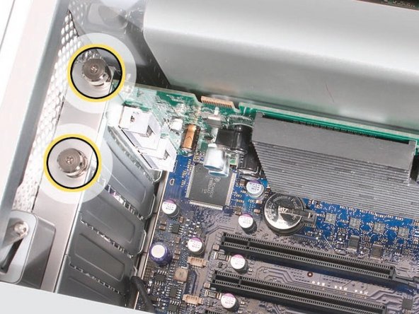
Using a Phillips P0 screwdriver, loosen the PCI Express cover retaining plate and remove it.
-
There is a tab at the top that the metal plate latches into. You'll need to unscrew the 2 screws and slide the plate down out of the tab.
-
-
Questo passaggio è privo di traduzione. Aiuta a tradurlo
-
1) Release the small locking clip at the front of the card’s logic board connector by pushing the clip up toward the media shelf.
-
2) Holding the card by the top corners, pull up the card and remove it from its expansion slot.
-
-
Questo passaggio è privo di traduzione. Aiuta a tradurlo
-
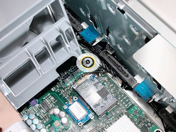
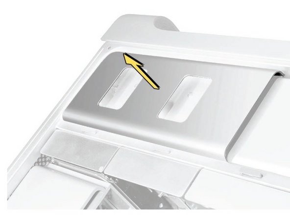
Using a long-handled, magnetized #1 Phillips screwdriver, remove the screw at the top rear of the front fan assembly that mounts the assembly to the logic board.
-
Remove the second Phillips screw at the bottom front of the assembly.
-
-
-
Questo passaggio è privo di traduzione. Aiuta a tradurlo
-
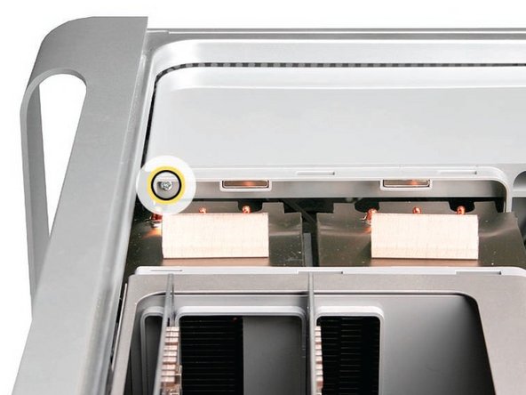
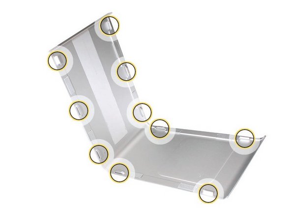
Place the fingers of one hand under the lip of the heatsink cover nearest the logic board. Lift the lip slightly toward the media shelf to release the tabs and magnets under the top face of the cover
-
With your fingers still under the cover’s bottom lip, lift the cover straight up to release the remaining tabs and magnets under the front face of the cover
-
Remove the cover from the enclosure.
-
-
Questo passaggio è privo di traduzione. Aiuta a tradurlo
-
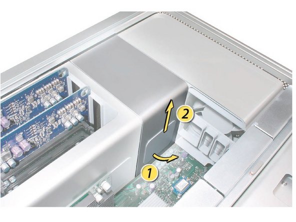
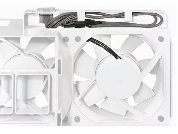
Remove the screws holding the fan enclosure in place. Mine had one at the top which screwed directly into the logic board, and another at the bottom (underneath the left yellow arrow on image 1). Place one hand on each end of the fan, lift straight up, and remove the fan from the enclosure.
-
-
Questo passaggio è privo di traduzione. Aiuta a tradurlo
-
Make sure the latch on the back panel is up, so that the drives and carriers are unlocked.
-
Pull the optical drive carrier part way out of the computer.
-
Disconnect the power and ribbon cables from the optical drive(s) and remove the carrier.
-
-
Questo passaggio è privo di traduzione. Aiuta a tradurlo
-
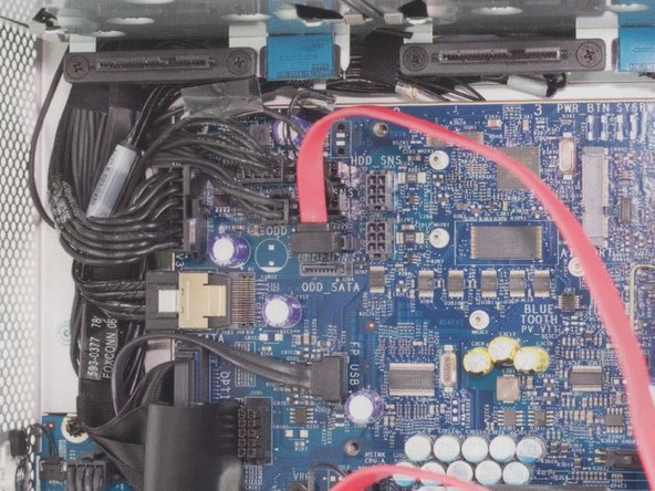
Now that you have fully exposed the logic board, look for the 2 SATA ports, circled here.
-
Insert the L shaped SATA cable into the top SATA port on the logic board.
-
-
Questo passaggio è privo di traduzione. Aiuta a tradurlo
-
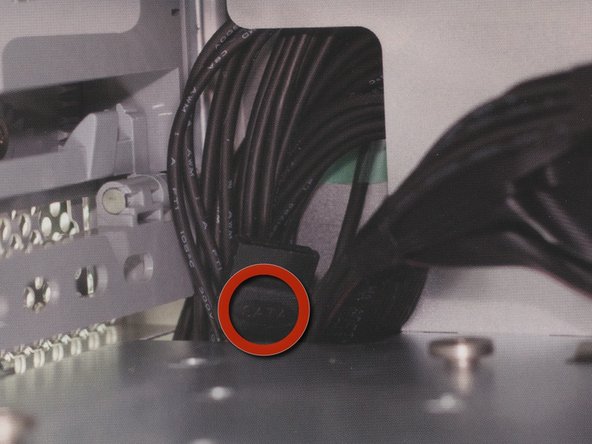
Start routing the SATA cable that you have already attached to the logic board up through the corner of the optical bay, following the existing wires.
-
Make sure you have the cable all the way tucked in behind the connector before proceeding. See the first graphic as an example.
-
-
Questo passaggio è privo di traduzione. Aiuta a tradurlo
-
Insert your new SATA optical drive into the carrier in the empty lower bay.
-
-
Questo passaggio è privo di traduzione. Aiuta a tradurlo
-
Using a paper clip, insert the paper clip into the emergency eject hole, which will release the drive door 1/2''.
-
Using your finger tips, pull the tray out about 2''
-
Then in accordance with the optical drive design remove the drive plate door.
-
-
Questo passaggio è privo di traduzione. Aiuta a tradurlo
-
Connect the power converter cable to the already provided secondary power connector.
-
-
Questo passaggio è privo di traduzione. Aiuta a tradurlo
-
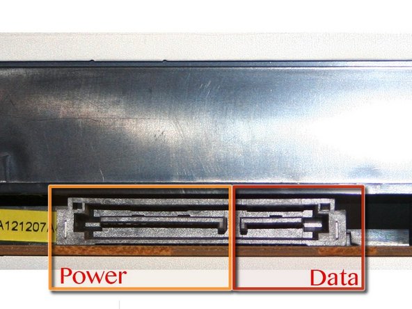
Insert the SATA cable and the power cable in the new drive.
-
-
Questo passaggio è privo di traduzione. Aiuta a tradurlo
-
Set the optical drive assembly into the optical drive bay. There are two screws that line up onto a track in the bottom of the bay.
-
Fully insert so the drive assembly is flush with the bay.
-
New optical drive is installed. Reassemble Mac Pro.
-


Annulla: non ho completato questa guida.
Altre 17 persone hanno completato questa guida.

2 Commenti
Just did this with my 2007 Mac Pro and the steps are the same.
I used straight SATA cables (since I had two lying around), which get bent a bit by the fan assembly. It should work ok if you're real careful with the assembly steps, but if you have a choice, get a SATA cable with an L-shaped end as shown in the guide.
Many thanks Joshua. I have also found a UK company able to supply a Blu-Ray player with instructions for installation.
Best regards from Steve in Brighton, England.