Questa versione può contenere modifiche errate. Passa all'ultima istantanea verificata.
Cosa ti serve
-
Questo passaggio è privo di traduzione. Aiuta a tradurlo
-
Press down on the battery cover and slide outwards to open.
-
-
Questo passaggio è privo di traduzione. Aiuta a tradurlo
-
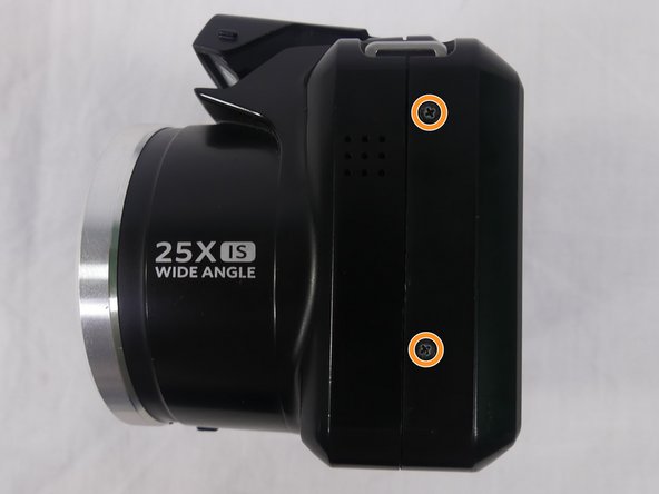
Remove a total of four 5mm JIS #000 screws from around the camera:
-
Two screws from the right side.
-
Two screws from the left side.
-
-
Questo passaggio è privo di traduzione. Aiuta a tradurlo
-
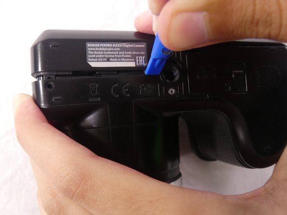
Remove the single 5mm Phillips #00 screw from the bottom.
-
-
Questo passaggio è privo di traduzione. Aiuta a tradurlo
-
Open the flash module.
-
Remove the two 6mm JIS #00 screws found inside of the flash housing.
-
-
Questo passaggio è privo di traduzione. Aiuta a tradurlo
-
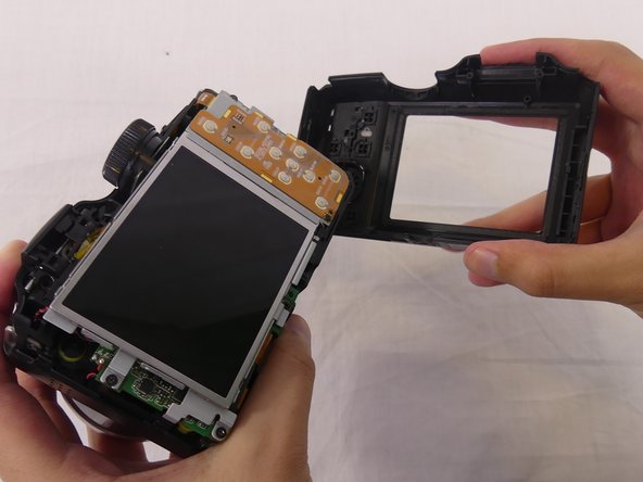
Use a plastic opening tool to pry apart both halves of the camera.
-
Remove the back panel.
-
-
-
Questo passaggio è privo di traduzione. Aiuta a tradurlo
-
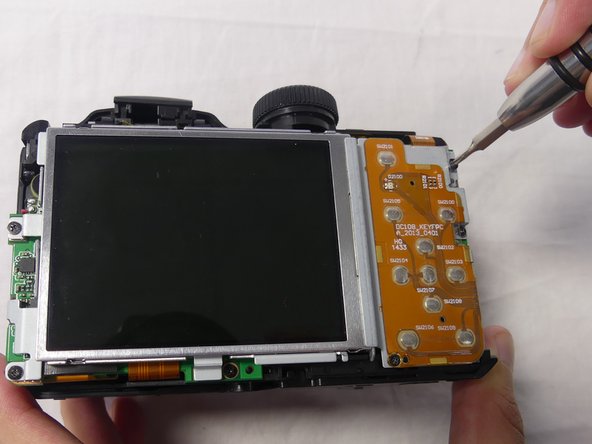
Remove these three JIS #000 screws from the control board:
-
5mm screw.
-
4mm screw.
-
2mm screw.
-
-
Questo passaggio è privo di traduzione. Aiuta a tradurlo
-
Pull the small metal switch plate to the side.
-
-
Questo passaggio è privo di traduzione. Aiuta a tradurlo
-
Pry the LCD screen out of the metal housing plate with a plastic opening tool.
-
-
Questo passaggio è privo di traduzione. Aiuta a tradurlo
-
Use a spudger to flip up the retaining flap on the display ribbon cable ZIF socket.
-
Pull the orange cable out of the socket.
-
-
Questo passaggio è privo di traduzione. Aiuta a tradurlo
-
Remove three 4mm JIS #000 screws from the metal housing plate.
-
-
Questo passaggio è privo di traduzione. Aiuta a tradurlo
-
Lift the metal housing plate out using your hands.
-
-
Questo passaggio è privo di traduzione. Aiuta a tradurlo
-
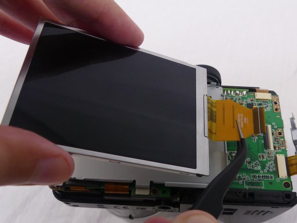
Disconnect the orange cable, connecting the small metal switch plate to the motherboard, by pulling it outwards with tweezers.
-
-
Questo passaggio è privo di traduzione. Aiuta a tradurlo
-
Disconnect two orange cables, one at the top and the other at the bottom of the motherboard, by pulling them outwards with tweezers.
-
Use a spudger to flip up the retaining flap on the ribbon cable ZIF socket.
-
-
Questo passaggio è privo di traduzione. Aiuta a tradurlo
-
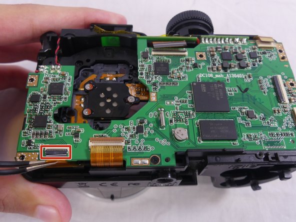
Remove the rectangular black cushion pad on the bottom left of the motherboard by pulling it upwards with your hands.
-
Use a spudger to flip up the retaining flap on the ribbon cable ZIF socket.
-
Disconnect the orange cable by pulling it outwards with tweezers.
-
-
Questo passaggio è privo di traduzione. Aiuta a tradurlo
-
Remove the two 4mm JIS #000 screws from the motherboard.
-
-
Questo passaggio è privo di traduzione. Aiuta a tradurlo
-
Desolder two pairs of electrical cable connections on the top left of the motherboard using the soldering iron.
-
Desolder the metal connector joining the two parts of the motherboard using the soldering iron.
-


Annulla: non ho completato questa guida.
Altre 5 persone hanno completato questa guida.
Team

USF Tampa, Team S1-G1, Cagle Spring 2018 Membro di USF Tampa, Team S1-G1, Cagle Spring 2018
USFT-CAGLE-S18S1G1
4 Membri
7 Guide realizzate