Questa versione può contenere modifiche errate. Passa all'ultima istantanea verificata.
Cosa ti serve
-
Questo passaggio è privo di traduzione. Aiuta a tradurlo
-
Slide the back cover down to remove it.
-
Lift and remove the battery. Then remove the SIM card by sliding it out of its slot.
-
Locate SD card on the lower right. Press in to eject and remove it.
-
-
Questo passaggio è privo di traduzione. Aiuta a tradurlo
-
Remove the four 6-mm Torx screws located at the corners of the phone and set them aside.
-
Remove the two 4-mm Torx screws located at the two long sides toward the middle of the phone. Set them aside.
-
-
Questo passaggio è privo di traduzione. Aiuta a tradurlo
-
Use a pry tool or your fingers to remove the antenna cover and antenna component from the bottom of the phone.
-
Insert a pry tool or your finger nail into the gap along the edge of the phone. Lift around the edges to loosen and remove the back plate.
-
-
-
Questo passaggio è privo di traduzione. Aiuta a tradurlo
-
Remove the two Phillips head 3 mm screws located on the bottom circuit board.
-
Locate the small ribbon cable just below the serial number barcode. Use a safe removal tool or precision flathead to gently detach the cable.
-
-
Questo passaggio è privo di traduzione. Aiuta a tradurlo
-
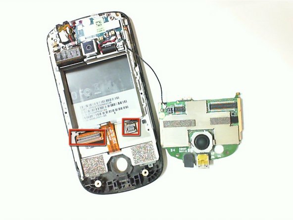
Lift up the circuit board gently from the right. You will notice some resistance due to the two ribbon cables attached underneath the circuit board. Continue to lift gently on the right until the ribbons detach and the resistance is released.
-
-
Questo passaggio è privo di traduzione. Aiuta a tradurlo
-
Flip the circuit board over to reveal the trackball.
-
If you want to clean the trackball, use an air duster and gently spray it. Keep a distance of 2-4 inches between the duster and trackball.
-
-
Questo passaggio è privo di traduzione. Aiuta a tradurlo
-
To remove the trackball, lay the circuit board face down and locate the two prongs as shown in the picture.
-
Use a precision flathead screwdriver to dislodge the prongs from the circuit board and push the prongs through the slots. The trackball should detach from the circuit board.
-
-
Questo passaggio è privo di traduzione. Aiuta a tradurlo
-
Insert a new trackball by guiding the prongs through the slots on the circuit board.
-
Once the trackball is in place, gently press down to ensure the trackball is secure.
-
Verify the prongs are latched to the circuit board.
-


Annulla: non ho completato questa guida.
Un'altra persona ha completato questa guida.
Team

Cal Poly, Team 2-9, Propen Fall 2012 Membro di Cal Poly, Team 2-9, Propen Fall 2012
CPSU-PROPEN-F12S2G9
3 Membri
10 Guide realizzate