Introduzione
Replace the LCD in your HP Mini 1000.
Cosa ti serve
-
-
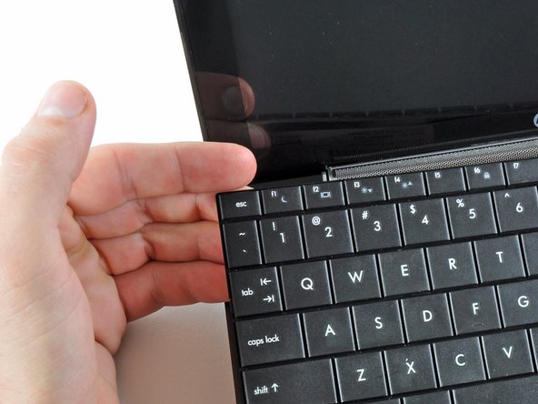
With the case closed, place the Mini 1000 top-side down on a flat surface.
-
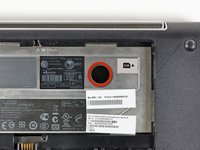
Push both of the battery release latches toward each other.
-
-
-
Remove the following two screws:
-
One 6 mm Phillips screw
-
One 4 mm Phillips screw
-
-
-
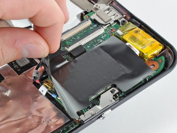
Use your fingernail or the flat end of a spudger to flip up the retaining flap on the SIM card ribbon cable ZIF socket.
-
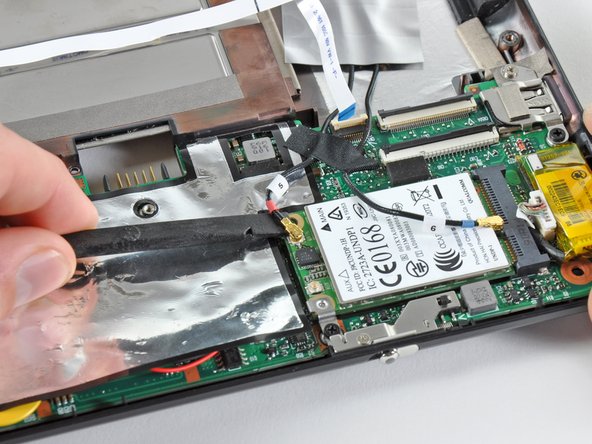
Pull the SIM card ribbon cable out of its socket and peel it off the top of the hard drive enclosure.
-
-
-
Using the sharp tip of a spudger, pry and remove the four plastic screw covers from the underside of the HP Mini 1000.
-
The two bottom covers are short in height and are notched to prevent incorrect insertion
-
The upper right cover is taller in height and is notched.
-
The upper left cover is taller in height and is not notched.
-
-
-
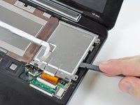
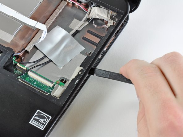
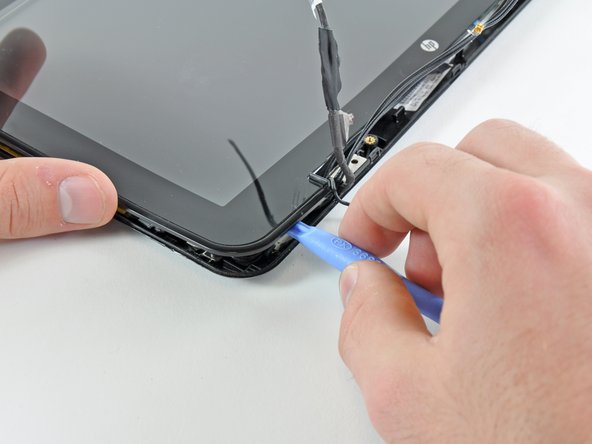
Wedge the flat end of a spudger in between the upper case and lower case near the bottom right corner of the display.
-
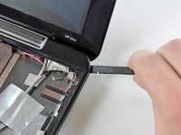
Carefully pry and rock the spudger upwards to create a small gap between the upper case and lower case.
-
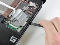
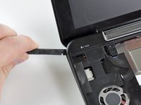
Continue the previously described motion along the right edge of the upper case to release the clips securing the upper case to the lower case.
-
-
-
-
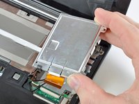
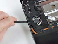
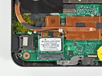
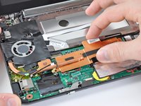
Remove the two 2.5 mm Phillips screws securing the heat sink to the motherboard.
-
-
-
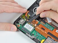
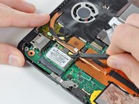
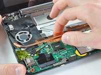
Carefully lift the heat sink off the face of the motherboard and de-route the curved section from next to the fan.
-
Before reinstalling the heat sink, be sure to apply a new layer of thermal paste to the CPU. We have a thermal paste guide that makes it easy.
-
-
-
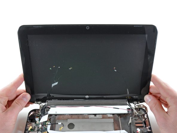
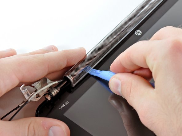
Use the edge of a plastic opening tool to pry the left side of the speaker grill away from the display assembly.
-
-
-
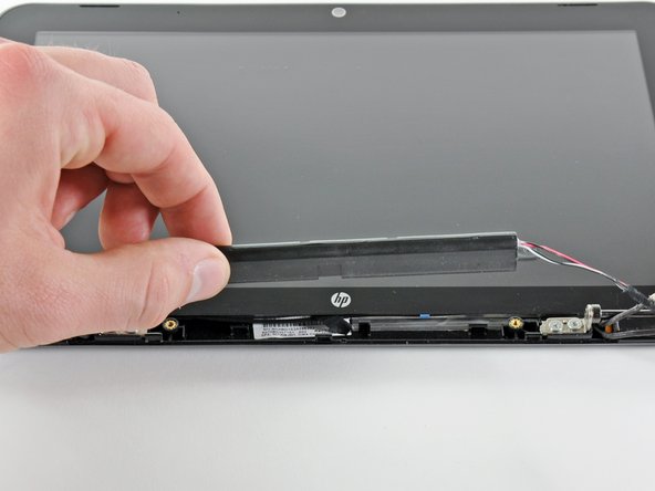
Remove the two 4.5 mm Phillips screws securing the speaker assembly to the display.
-
Remove the speaker assembly.
-
-
-
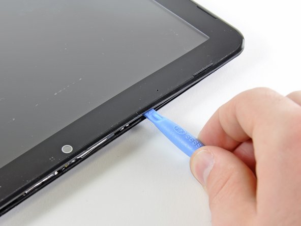
In the following steps you will pry the front display bezel off the rear section of the display. The locations of the retaining clips are highlighted in red.
-
-
-
Use the sharp end of a spudger to flip up the plastic flap that rests on top of the camera board cable ZIF socket.
-


To reassemble your device, follow these instructions in reverse order.
Annulla: non ho completato questa guida.
Un'altra persona ha completato questa guida.
