Questa versione può contenere modifiche errate. Passa all'ultima istantanea verificata.
Cosa ti serve
-
Questo passaggio è privo di traduzione. Aiuta a tradurlo
-
Before removing the screen, be sure to turn off and unplug your device.
-
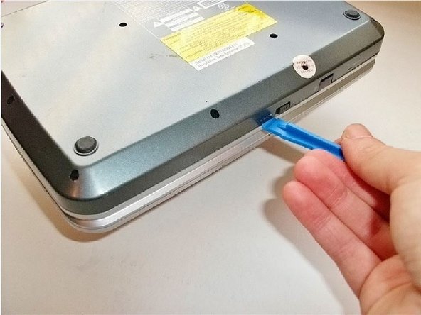
Flip your device over, so the bottom is facing up.
-
-
Questo passaggio è privo di traduzione. Aiuta a tradurlo
-
Remove the back cover held by thirteen 3.175 mm head, 9.525 mm length pan-head Phillips screws.
-
-
Questo passaggio è privo di traduzione. Aiuta a tradurlo
-
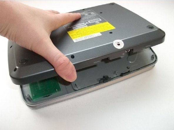
Use a plastic opening tool to pop open the back case.
-
Do not separate the back cover completely, wires are still connected to both sides.
-
-
-
Questo passaggio è privo di traduzione. Aiuta a tradurlo
-
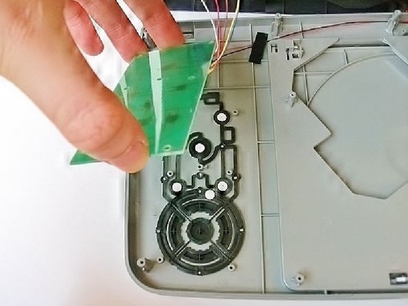
Hold the back cover upright and remove the black tape connecting the wire group to the cover.
-
Remove the bottom two pieces of tape connecting wires to the CD tray.
-
-
Questo passaggio è privo di traduzione. Aiuta a tradurlo
-
Locate the small circuit board on the underside of the buttons.
-
Remove the circuit board for the buttons, held by six 3.175 mm head, 4.762 mm length flat-head Phillips screws.
-
-
Questo passaggio è privo di traduzione. Aiuta a tradurlo
-
Remove the three wire connections that are located on the main (largest) circuit board.
-
The connection can be gently removed with a plastic opening tool or with your fingers by pinching the ends and pulling.
-
-
Questo passaggio è privo di traduzione. Aiuta a tradurlo
-
Remove the optical disc drive by lifting it off the three pegs on the bottom case.
-
-
Questo passaggio è privo di traduzione. Aiuta a tradurlo
-
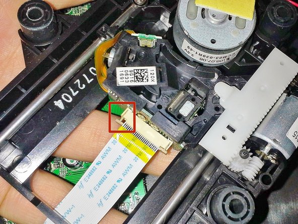
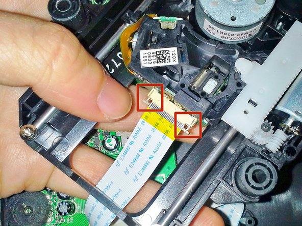
Now that the optical drive is removed from the case, flip it over and locate the ribbon cable.
-
Gently pull out the two sides of the brown tab underneath the ribbon cable, see images for detail.
-
Once both sides of the tab are out, it should require no force to pull the ribbon cable out of the connection on the optical drive.
-
-
Questo passaggio è privo di traduzione. Aiuta a tradurlo
-
Now the optical drive should be removed and still connected to the circuit board which was underneath the buttons.
-
Desolder the optical drive wires from the circuit board.
-


Annulla: non ho completato questa guida.
Un'altra persona ha completato questa guida.
Team

Cal Poly, Team 8-10, Regan Spring 2014 Membro di Cal Poly, Team 8-10, Regan Spring 2014
CPSU-REGAN-S14S8G10
4 Membri
16 Guide realizzate