Questa versione può contenere modifiche errate. Passa all'ultima istantanea verificata.
Cosa ti serve
-
Questo passaggio è privo di traduzione. Aiuta a tradurlo
-
Remove the six 13 mm case screws with a #0 Phillips screwdriver from the side of the power screwdriver.
-
-
Questo passaggio è privo di traduzione. Aiuta a tradurlo
-
Using a plastic opening tool, separate the case in two to expose the internals of the cordless screwdriver.
-
-
-
Questo passaggio è privo di traduzione. Aiuta a tradurlo
-
Remove printed circuit board, LED, battery, and motor assembly from the screwdriver casing.
-
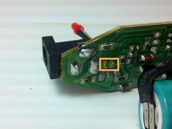
Use a soldering iron to melt the solder from the LED's two pins on the printed circuit board.
-
Remove the LED from the circuit board while the solder is still melted.
-
-
Questo passaggio è privo di traduzione. Aiuta a tradurlo
-
Place the positive leg of the new LED through the positive hole in the printed circuit board and solder it into place.
-
Place the negative leg of the LED through the negative hold in the printed circuit board and solder it into place.
-


Annulla: non ho completato questa guida.
Un'altra persona ha completato questa guida.
Team

Michigan Tech, Team 5-5, Lauer Spring 2014 Membro di Michigan Tech, Team 5-5, Lauer Spring 2014
MTU-LAUER-S14S5G5
3 Membri
5 Guide realizzate
Un commento
Hello, I would ask the author about the type and model number of the electronic element marked as Q1 on the PCB (transistor or thyristor) on the third picture in Step 3 of this article, because mine is burnt out, and on this picture can't be read anything.
Greetings,
Plam