Salta al contenuto principale

Questa guida ha delle modifiche più recenti. Passa all'ultima versione non verificata.

Disassembling KDDI Kyocera A5521K Logic Board

Cosa ti serve

  1. Disassembling KDDI Kyocera A5521K Logic Board, Disassembling KDDI Kyocera A5521K Battery: passo 1, immagine 1 di 3 Disassembling KDDI Kyocera A5521K Logic Board, Disassembling KDDI Kyocera A5521K Battery: passo 1, immagine 2 di 3 Disassembling KDDI Kyocera A5521K Logic Board, Disassembling KDDI Kyocera A5521K Battery: passo 1, immagine 3 di 3
    • Turn the phone over to expose the battery cover.

    • Apply pressure to the back of the battery cover to slide it down.

    • The battery cover is now separate from the phone.

  2. Disassembling KDDI Kyocera A5521K Logic Board: passo 2, immagine 1 di 3 Disassembling KDDI Kyocera A5521K Logic Board: passo 2, immagine 2 di 3 Disassembling KDDI Kyocera A5521K Logic Board: passo 2, immagine 3 di 3
    • Remove the battery by pushing it up and out from the bottom.

    • The battery, cover, and phone should now be separated.

  3. Disassembling KDDI Kyocera A5521K Logic Board, Back Plate: passo 3, immagine 1 di 2 Disassembling KDDI Kyocera A5521K Logic Board, Back Plate: passo 3, immagine 2 di 2
    • Remove the four screws with the Y0 screwdriver.

  4. Disassembling KDDI Kyocera A5521K Logic Board: passo 4, immagine 1 di 2 Disassembling KDDI Kyocera A5521K Logic Board: passo 4, immagine 2 di 2
    • Remove the black, rubber screw caps towards the top of the back of the phone to reveal two additional screws.

    • Remove the two screws with a Y0 screwdriver.

  5. Disassembling KDDI Kyocera A5521K Logic Board: passo 5, immagine 1 di 3 Disassembling KDDI Kyocera A5521K Logic Board: passo 5, immagine 2 di 3 Disassembling KDDI Kyocera A5521K Logic Board: passo 5, immagine 3 di 3
    • Rotate the phone 180 degrees.

    • Carefully separate the back plate from the remainder of the phone.

    • The back plate should now be detached from the rest of the phone.

  6. Disassembling KDDI Kyocera A5521K Logic Board, SD Card Slot: passo 6, immagine 1 di 3 Disassembling KDDI Kyocera A5521K Logic Board, SD Card Slot: passo 6, immagine 2 di 3 Disassembling KDDI Kyocera A5521K Logic Board, SD Card Slot: passo 6, immagine 3 di 3
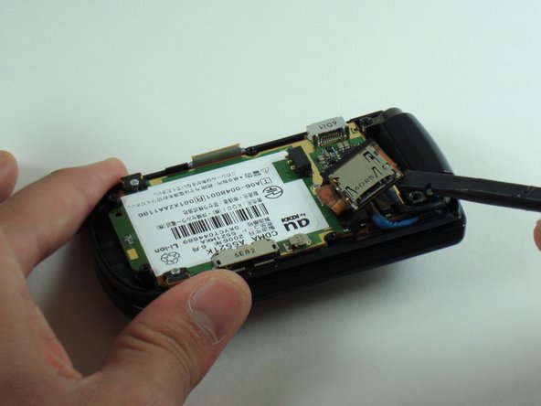
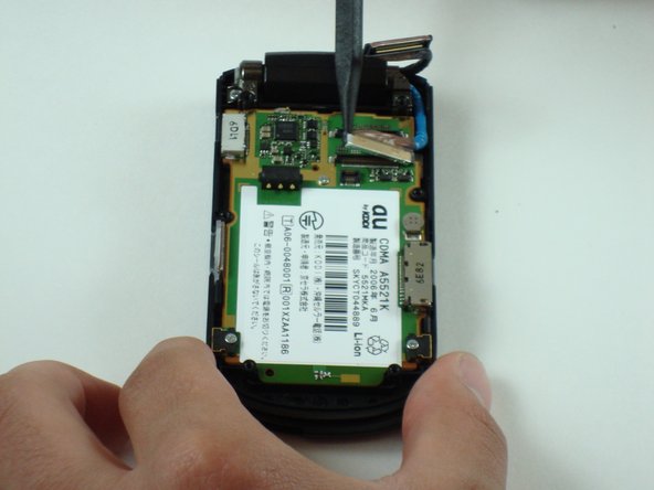
    • Rotate the phone approximately 45 degrees to the right.

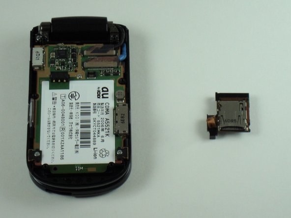
    • Gently pry up the SD card slot with a spudger.

  7. Disassembling KDDI Kyocera A5521K Logic Board, Logic Board: passo 7, immagine 1 di 3 Disassembling KDDI Kyocera A5521K Logic Board, Logic Board: passo 7, immagine 2 di 3 Disassembling KDDI Kyocera A5521K Logic Board, Logic Board: passo 7, immagine 3 di 3
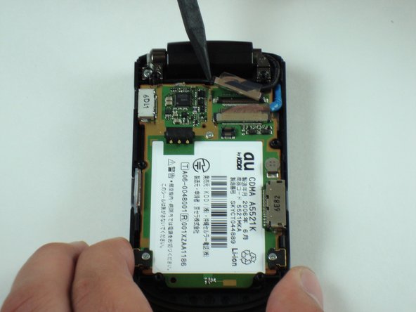
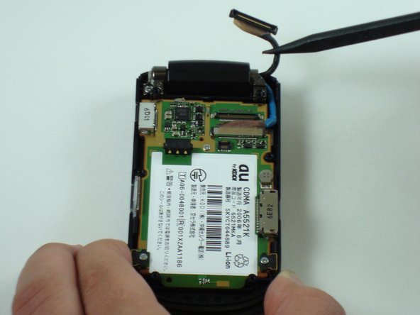
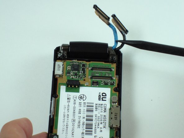
    • Lift up on the first connection shown using a pair of pliers.

    • Disconnect the first connection between the logic board and the wire using the pair of pliers.

  8. Disassembling KDDI Kyocera A5521K Logic Board: passo 8, immagine 1 di 3 Disassembling KDDI Kyocera A5521K Logic Board: passo 8, immagine 2 di 3 Disassembling KDDI Kyocera A5521K Logic Board: passo 8, immagine 3 di 3
    • Repeat the above steps for the second connection.

    • Use the pliers to pry up the connection.

    • Use the pliers to disconnect the connection between the logic board and the wire.

  9. Disassembling KDDI Kyocera A5521K Logic Board: passo 9, immagine 1 di 1
    • Lift up on the bottom of the logic board with a spudger.

    • Gently remove the rest of the logic board from the phone.

  10. Disassembling KDDI Kyocera A5521K Logic Board: passo 10, immagine 1 di 2 Disassembling KDDI Kyocera A5521K Logic Board: passo 10, immagine 2 di 2
    • The logic board should now be completely disconnected from the phone.

Conclusione

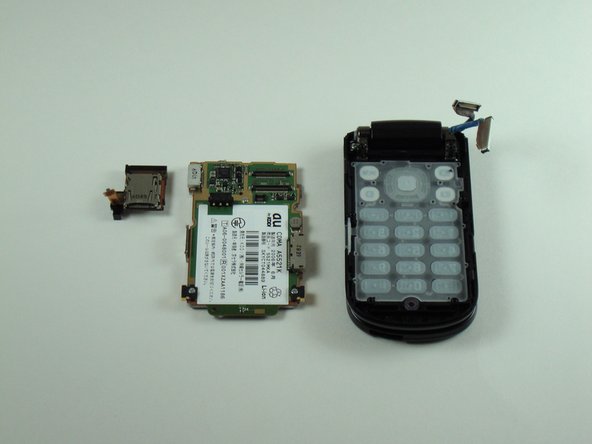
To reassemble your device, follow these instructions in reverse order.

Team

Cal Poly, Team 28-25, Regan Spring 2010 Membro di Cal Poly, Team 28-25, Regan Spring 2010

CPSU-REGAN-S10S28G25

4 Membri

20 Guide realizzate

0 Commenti

Aggiungi Commento

Visualizza Statistiche:

Ultime 24 Ore: 1

Ultimi 7 Giorni: 7

Ultimi 30 Giorni: 8

Tutti i Tempi: 1,782