Questa guida ha delle modifiche più recenti. Passa all'ultima versione non verificata.
Introduzione
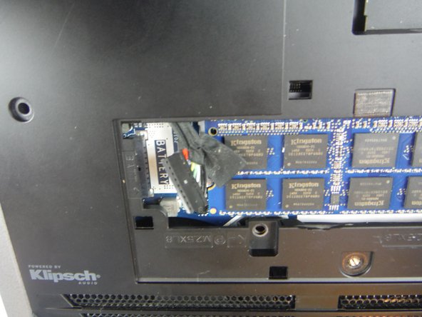
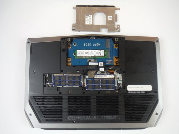
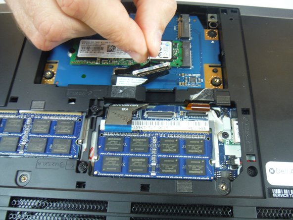
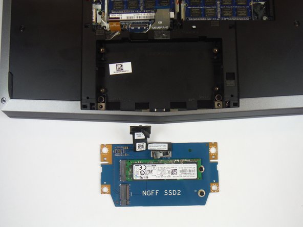
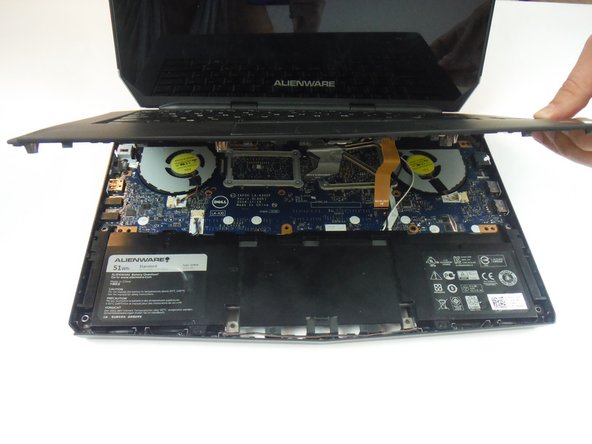
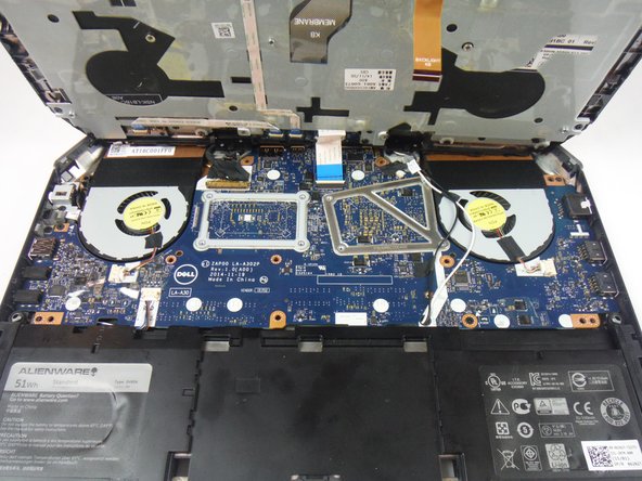
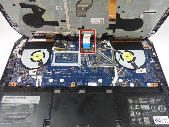
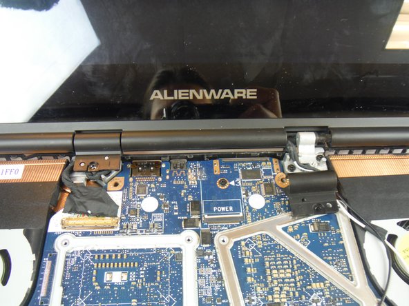
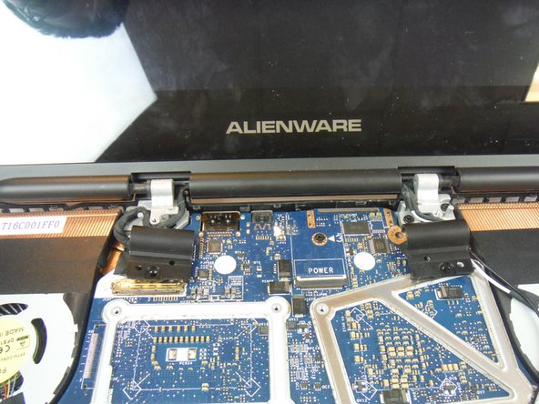
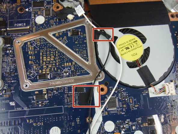
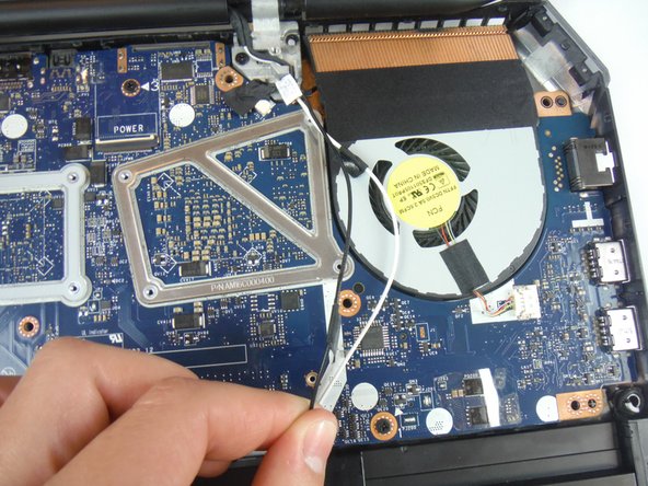
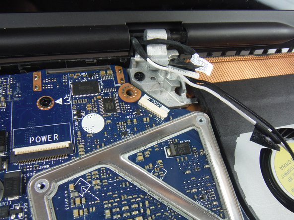
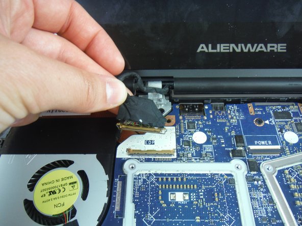
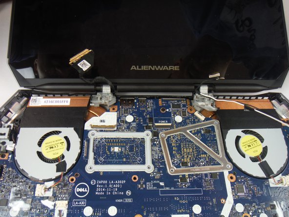
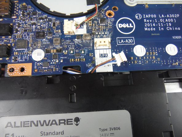
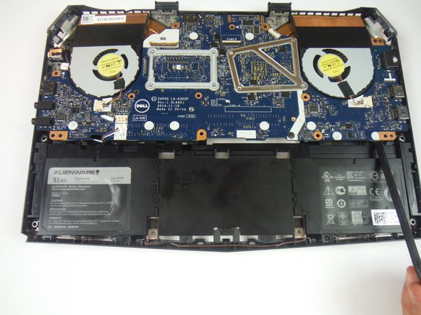
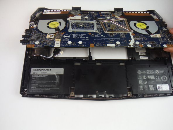
This guide will show the user how to replace a cracked, broken, or damaged computer base on a Dell Alienware 13 laptop.
Cosa ti serve


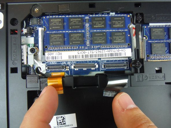

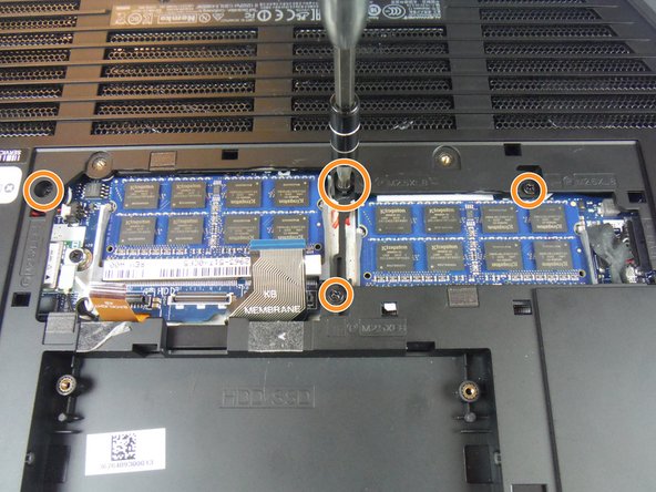
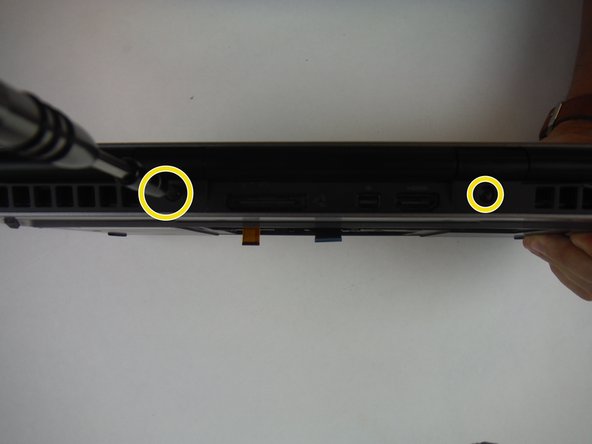

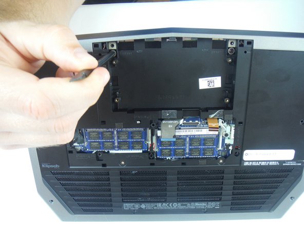


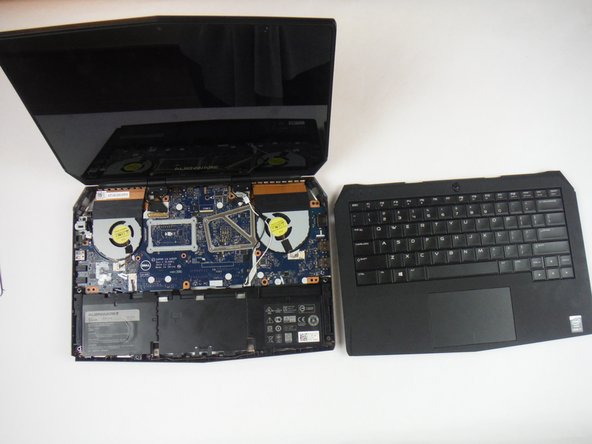


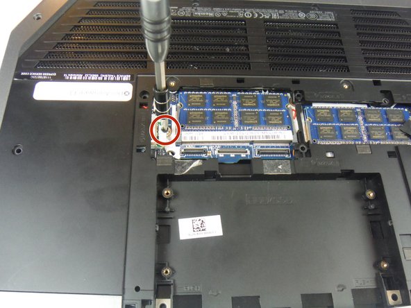

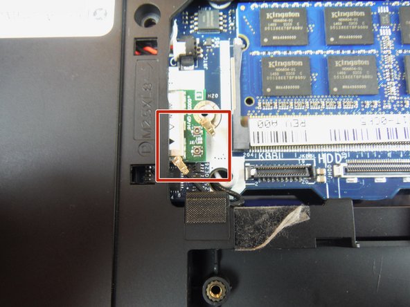


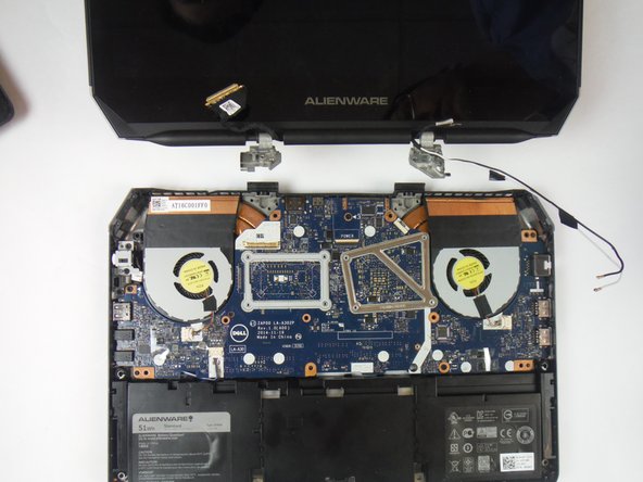


To reassemble your device, follow these instructions in reverse order.
To reassemble your device, follow these instructions in reverse order.
Annulla: non ho completato questa guida.
Altre 2 persone hanno completato questa guida.

Team

USF Tampa, Team 14-2, Eyestone Fall 2016 Membro di USF Tampa, Team 14-2, Eyestone Fall 2016
USFT-EYESTONE-F16S14G2
3 Membri
7 Guide realizzate