Questa versione può contenere modifiche errate. Passa all'ultima istantanea verificata.
Cosa ti serve
-
Questo passaggio è privo di traduzione. Aiuta a tradurlo
-
Remove (2) 5 mm Phillips head screws attaching the small access panel to the base using a Phillips # 1 screwdriver.
-
-
Questo passaggio è privo di traduzione. Aiuta a tradurlo
-
Remove the small access panel using a heavy duty spudger.
-
-
Questo passaggio è privo di traduzione. Aiuta a tradurlo
-
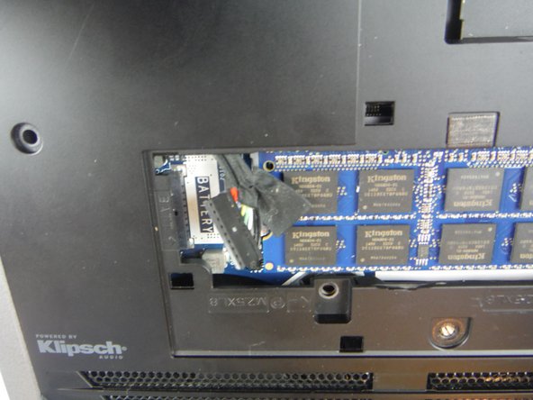
Disconnect the battery cable from the battery cable terminal.
-
-
Questo passaggio è privo di traduzione. Aiuta a tradurlo
-
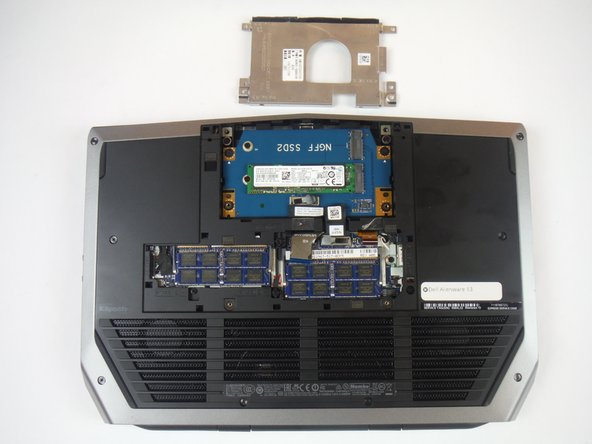
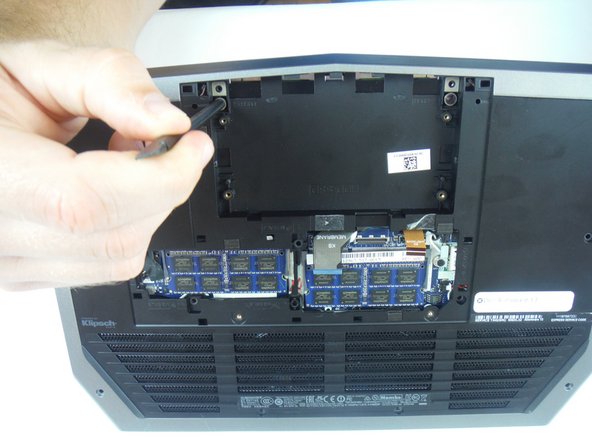
Remove (4) 6 mm Phillips head screws from the solid-state metal drive bracket, using a Phillips # 1 screwdriver.
-
-
Questo passaggio è privo di traduzione. Aiuta a tradurlo
-
Grab the pull tab to pivot the solid-state drive bracket upwards. Remove the bracket from the computer base.
-
-
Questo passaggio è privo di traduzione. Aiuta a tradurlo
-
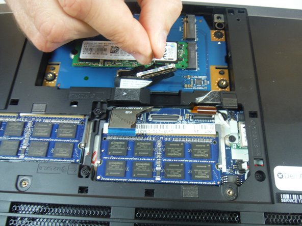
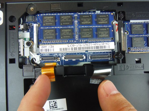
Using the pull tab, disconnect the black solid-state drive cable from the system board.
-
-
Questo passaggio è privo di traduzione. Aiuta a tradurlo
-
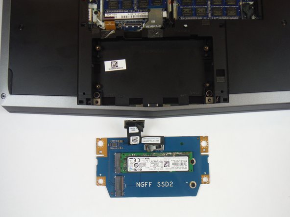
Remove (2) 3 mm Phillips head screws, using a Phillips # 0 screwdriver, that connect the solid-state drive assembly to the computer base.
-
-
-
Questo passaggio è privo di traduzione. Aiuta a tradurlo
-
Lift up on the solid-state drive assembly to remove it from the computer base.
-
-
Questo passaggio è privo di traduzione. Aiuta a tradurlo
-
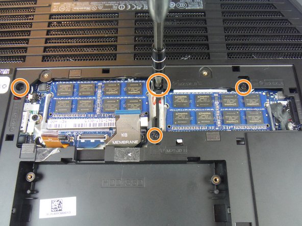
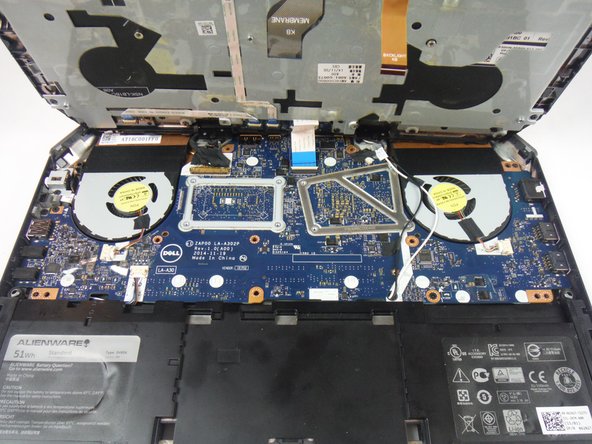
Locate two cables labeled, "KB Backlight" (orange) and "KB Membrane" (black). Lift up on the latches to disconnect the cables from the system board.
-
-
Questo passaggio è privo di traduzione. Aiuta a tradurlo
-
Remove (8) 9 mm Phillips head screws using a Phillips # 1 screwdriver, that secures the palm-rest assembly to the computer base.
-
Remove (4) 8 mm Phillips head screws using a Phillips # 1 screwdriver.
-
Remove (2) 7 mm Phillips head screws using a Phillips # 1 screwdriver.
-
-
Questo passaggio è privo di traduzione. Aiuta a tradurlo
-
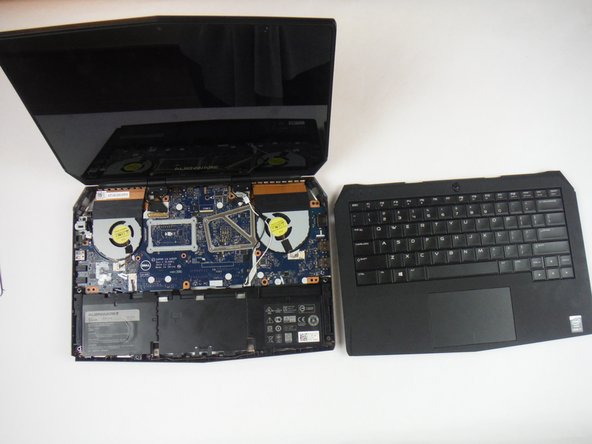
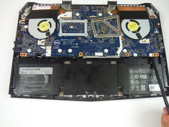
Lift the computer base slightly towards you and push the release tabs on the palm-rest assembly until it pops out using a spudger.
-
-
Questo passaggio è privo di traduzione. Aiuta a tradurlo
-
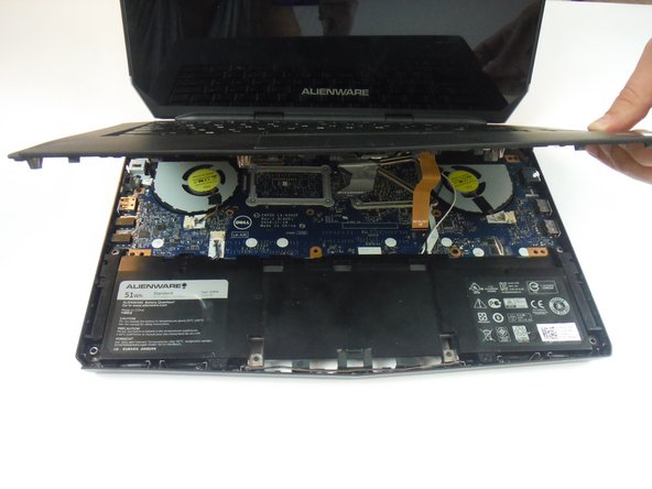
Turn the computer over and open the display as far as possible.
-
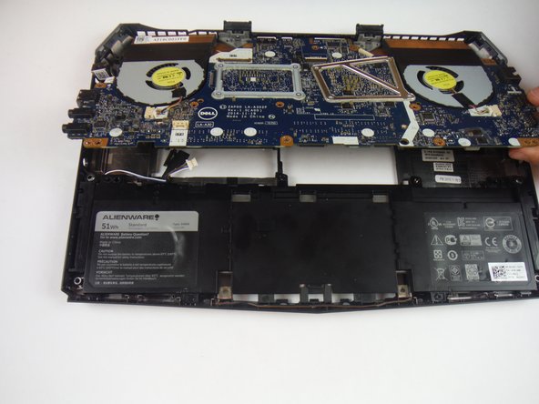
Using a plastic spudger, pry up along the edges of the palm-rest assembly.
-
Gently lift the palm-rest assembly.
-
-
Questo passaggio è privo di traduzione. Aiuta a tradurlo
-
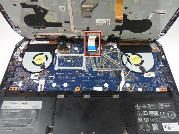
Lift the connector latch and disconnect the power-button board cable from the system board. Identified as a cable with a blue tab.
-
Lift the palm-rest assembly off the computer base.
-
-
Questo passaggio è privo di traduzione. Aiuta a tradurlo
-
Open the display as far as possible.
-
Remove (2) 3 mm Phillips head screws, using a Phillips head #0 screwdriver, that secure the hinge caps to the display hinges.
-
Slide and lift the hinge caps off the display hinges.
-
-
Questo passaggio è privo di traduzione. Aiuta a tradurlo
-
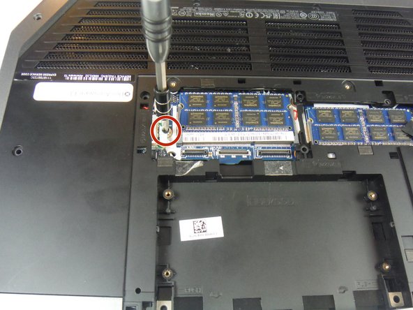
Close the display and turn the computer over.
-
Remove (1) 2 mm Phillips head screw, using a Phillips head # 0 screwdriver, that secures the wireless-card bracket to the wireless card.
-
-
Questo passaggio è privo di traduzione. Aiuta a tradurlo
-
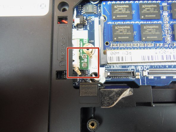
Disconnect the antenna cables from the wireless card using a heavy duty spudger. The wires can be removed by applying a force directed upward, away from the device.
-
-
Questo passaggio è privo di traduzione. Aiuta a tradurlo
-
Turn the computer over and open the display.
-
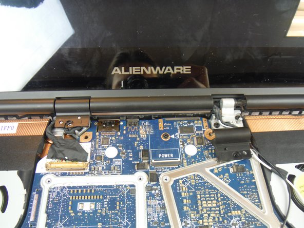
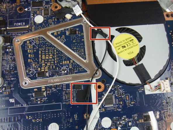
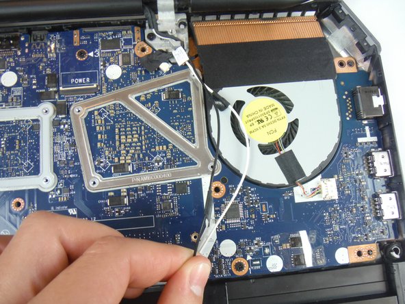
Peel off the adhesive tapes that secure the antenna cables to the system board.
-
-
Questo passaggio è privo di traduzione. Aiuta a tradurlo
-
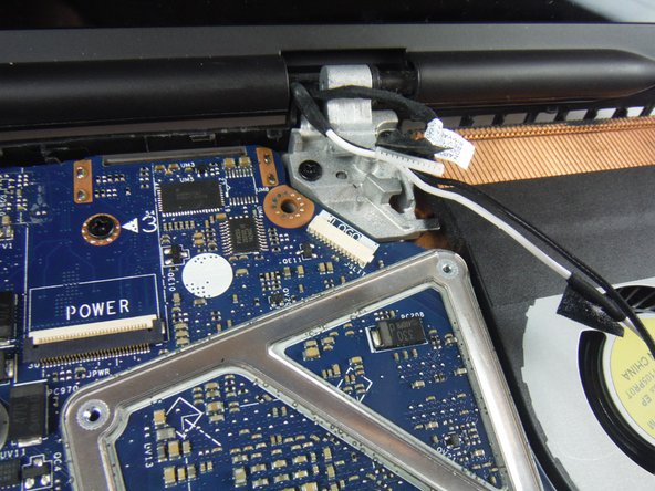
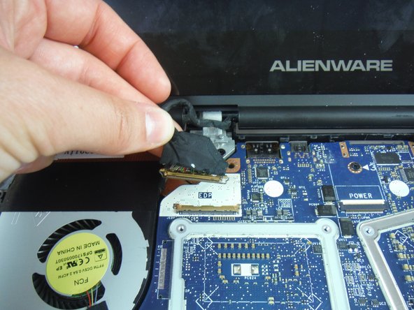
Lift the connector latch and disconnect the display cable from the system board.
-
Disconnect the logo-board cable from the system board.
-
Remove the antenna cables, display cable, and logo-board cable from the routing guides on the display hinges.
-
-
Questo passaggio è privo di traduzione. Aiuta a tradurlo
-
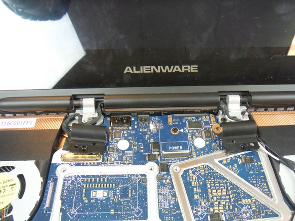
Remove (4) 8 mm Phillips head screws, using a Phillips # 1 screwdriver, that secure the display assembly to the computer base.
-
Lift the display assembly off the computer base.
-
-
Questo passaggio è privo di traduzione. Aiuta a tradurlo
-
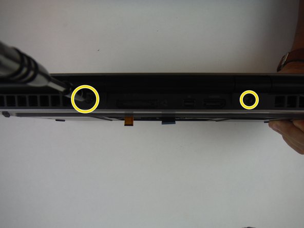
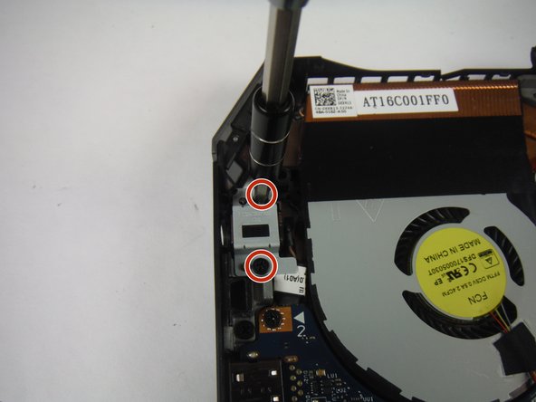
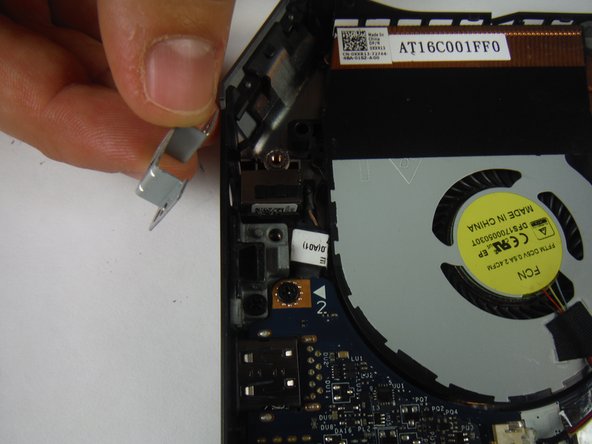
Remove the (2) 6 mm Phillips head screws securing the power adapter port bracket with a #1 Phillips screwdriver.
-
Lift and remove the power adapter port bracket.
-
-
Questo passaggio è privo di traduzione. Aiuta a tradurlo
-
Lift up and remove the power adapter port from the computer base.
-
-
Questo passaggio è privo di traduzione. Aiuta a tradurlo
-
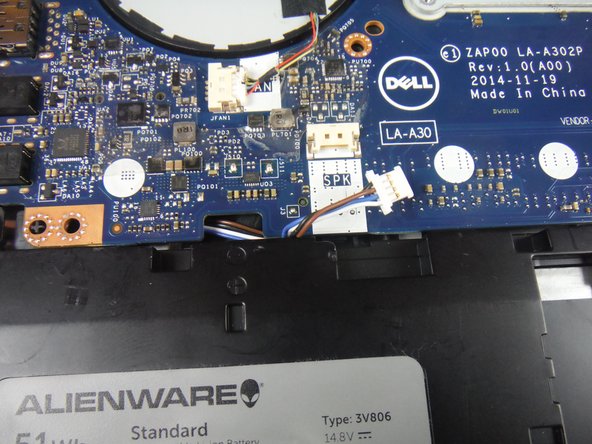
Disconnect the speaker cable connector from the service board.
-
-
Questo passaggio è privo di traduzione. Aiuta a tradurlo
-
Remove (3) 6 mm Phillips head screws securing the service board with a #1 Phillips screwdriver.
-
Lift up on the service board assembly using a heavy duty spudger and slide the board towards the battery to remove from the base.
-


Annulla: non ho completato questa guida.
Altre 2 persone hanno completato questa guida.

Team

USF Tampa, Team 14-2, Eyestone Fall 2016 Membro di USF Tampa, Team 14-2, Eyestone Fall 2016
USFT-EYESTONE-F16S14G2
3 Membri
7 Guide realizzate