Questa versione può contenere modifiche errate. Passa all'ultima istantanea verificata.
Cosa ti serve
-
Questo passaggio è privo di traduzione. Aiuta a tradurlo
-
Turn the base over. You will see four 11mm Phillips #0 screws, one in each corner.
-
Use a screwdriver to remove all four 11mm Phillips #0 screws.
-
-
Questo passaggio è privo di traduzione. Aiuta a tradurlo
-
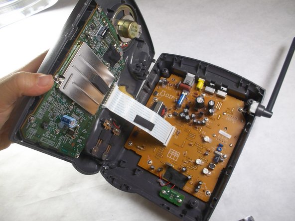
Locate an easy seam for entry and insert the metal spudger to separate the plastic. Use the spudger in multiple places if necessary.
-
-
-
Questo passaggio è privo di traduzione. Aiuta a tradurlo
-
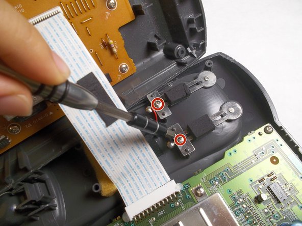
Locate the charging component towards the bottom of the grey, plastic, phone-shaped extrusion. It is composed of two metal pieces; each is fastened by a 5mm Phillips #0 screw.
-
Remove both 5mm Phillips #0 screws to release the metal pieces.
-
-
Questo passaggio è privo di traduzione. Aiuta a tradurlo
-
Cut the black and red wires to finish removal, and then solder your new replacement component.
-
For more help on soldering, please refer to the iFixit Solder and Desolder Guide.
-


Annulla: non ho completato questa guida.
Un'altra persona ha completato questa guida.
Team

IUPUI, Team 3-3, Harley Fall 2016 Membro di IUPUI, Team 3-3, Harley Fall 2016
IUPUI-HARLEY-F16S3G3
4 Membri
17 Guide realizzate