Questa guida ha delle modifiche più recenti. Passa all'ultima versione non verificata.
Introduzione
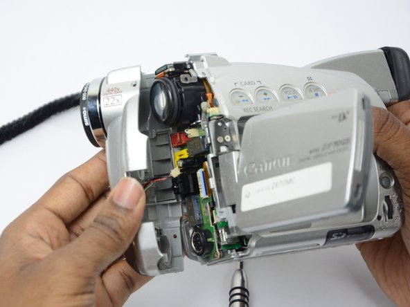
Use this guide to replace the LCD screen on your device.
Cosa ti serve
-
-
-
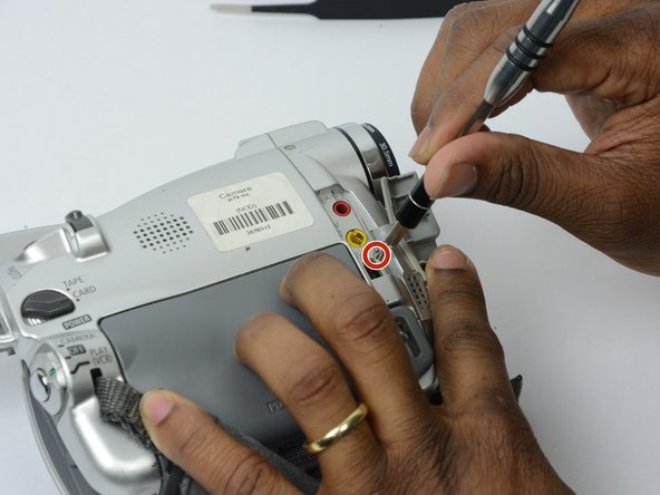
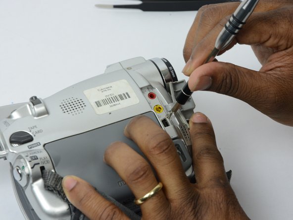
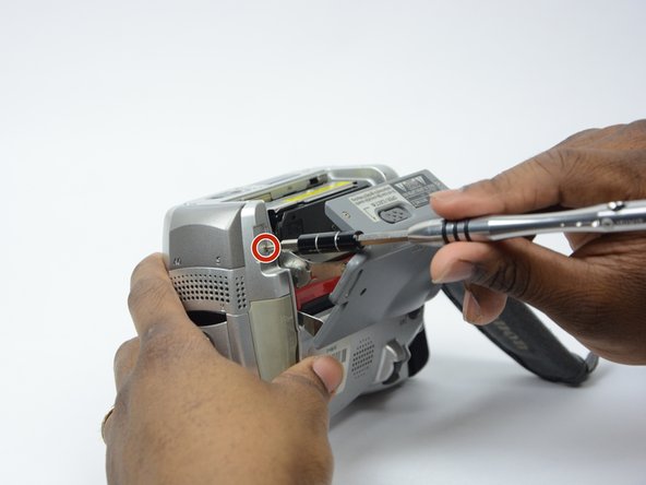
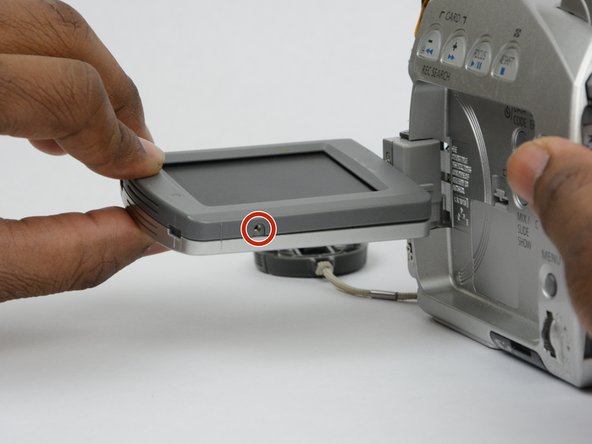
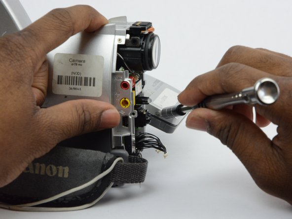
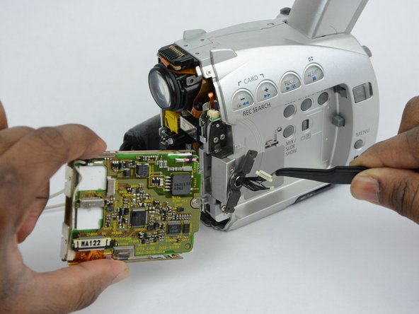
Open the LCD screen.
-
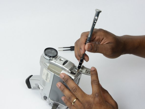
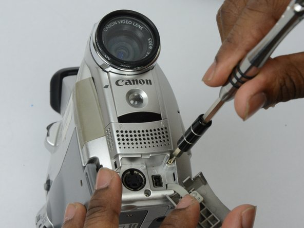
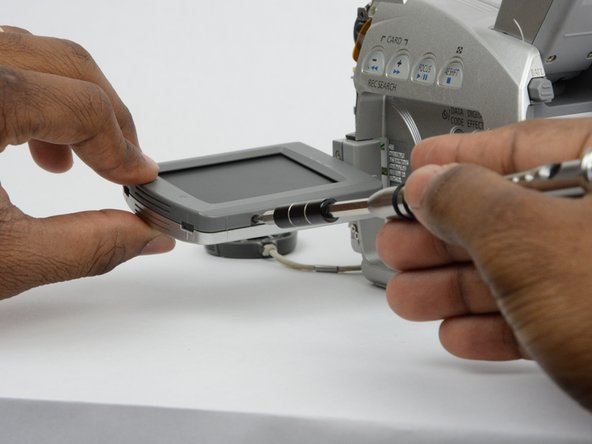
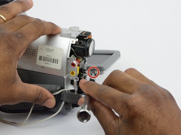
Locate and remove the 2.7 mm screw on the bottom of the LCD monitor.
-


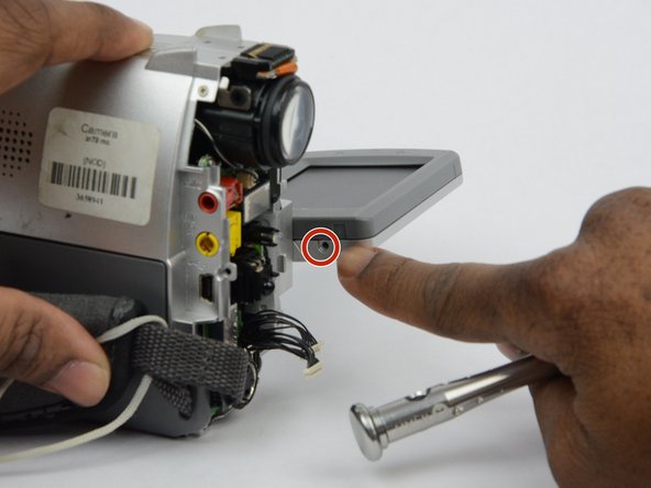


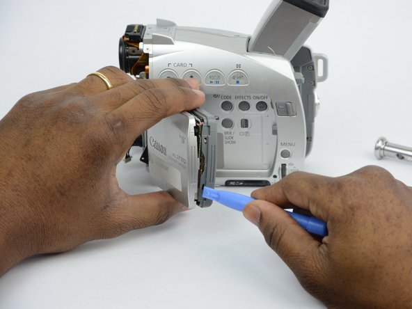
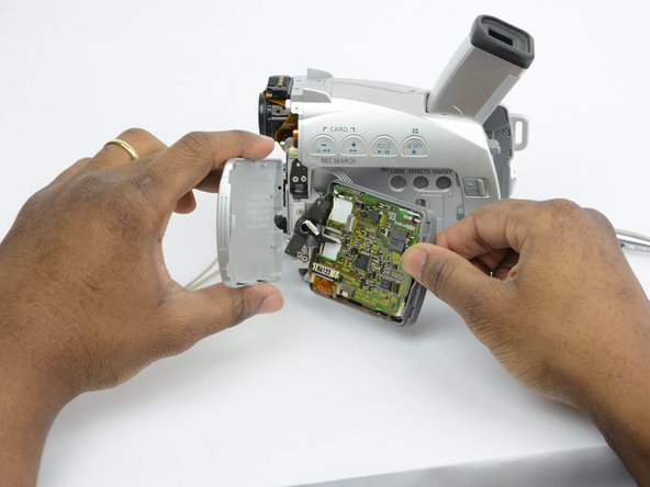

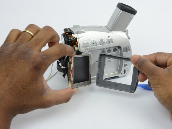
To reassemble your device, follow these instructions in reverse order.
To reassemble your device, follow these instructions in reverse order.
Annulla: non ho completato questa guida.
Un'altra persona ha completato questa guida.
Team

USF Tampa, Team S13-G2, Boczar Fall 2017 Membro di USF Tampa, Team S13-G2, Boczar Fall 2017
USFT-BOCZAR-F17S13G2
3 Membri
14 Guide realizzate