Questa versione può contenere modifiche errate. Passa all'ultima istantanea verificata.
Cosa ti serve
-
Questo passaggio è privo di traduzione. Aiuta a tradurlo
-
Turn the ZR70MC so that you can see the bottom of the camcorder.
-
Unscrew the 3.35 mm located in the top left portion of the camera.
-
-
Questo passaggio è privo di traduzione. Aiuta a tradurlo
-
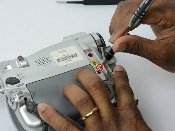
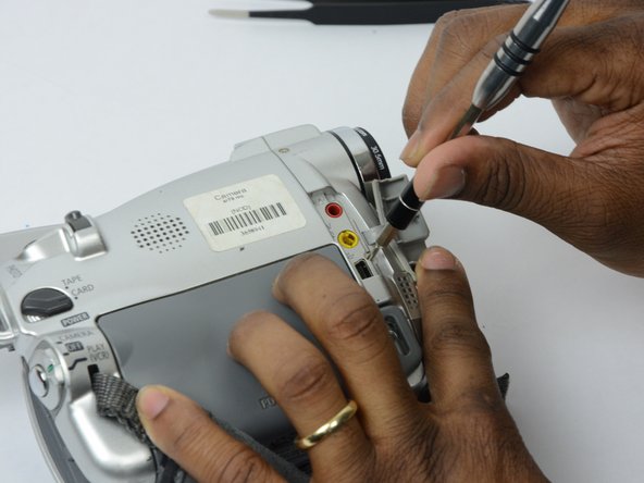
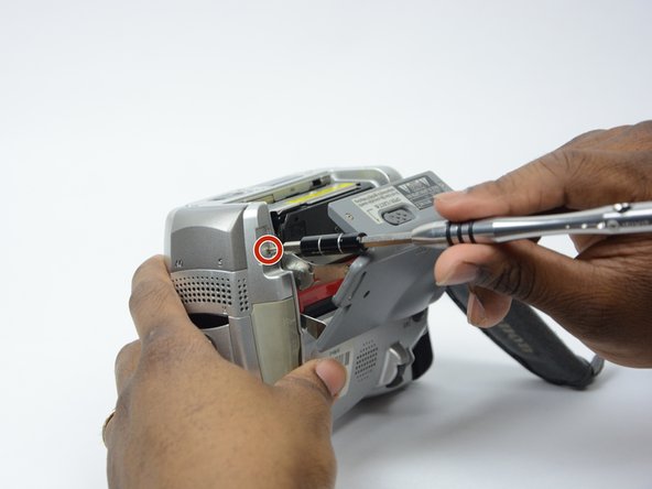
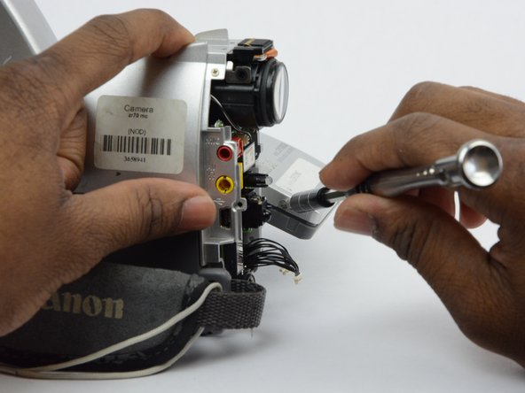
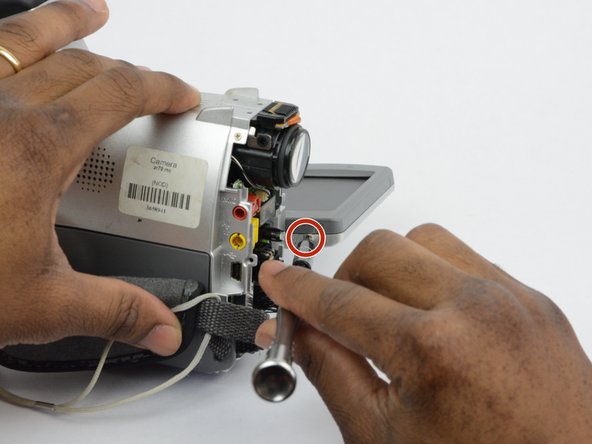
Turn the camera on the side and remove the cover for the audio inputs. There is a 2.65 mm screw located behind the cover.
-
Remove the 2.65 mm screw.
-
-
Questo passaggio è privo di traduzione. Aiuta a tradurlo
-
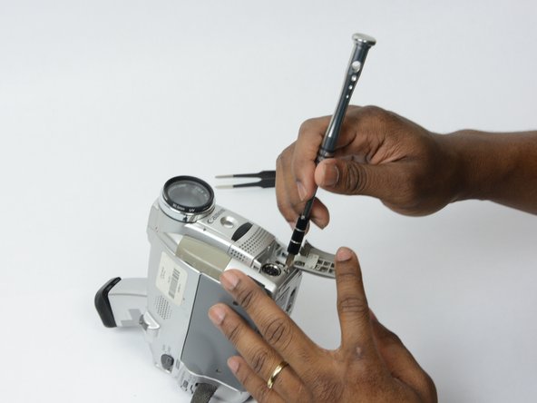
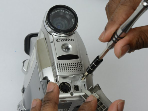
Remove the cover located on the front of the camcorder and remove the cover by pulling on the bottom groove.
-
Locate and remove the two 3.35 mm screws.
-
-
-
Questo passaggio è privo di traduzione. Aiuta a tradurlo
-
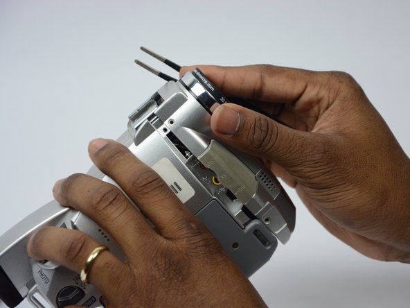
Turn the camcorder so that the bottom is facing up and open the tape cassette compartment.
-
There is one 3.35 mm screw located under the tape cassette panel on the front left side of the camcorder. Remove the screw.
-
-
Questo passaggio è privo di traduzione. Aiuta a tradurlo
-
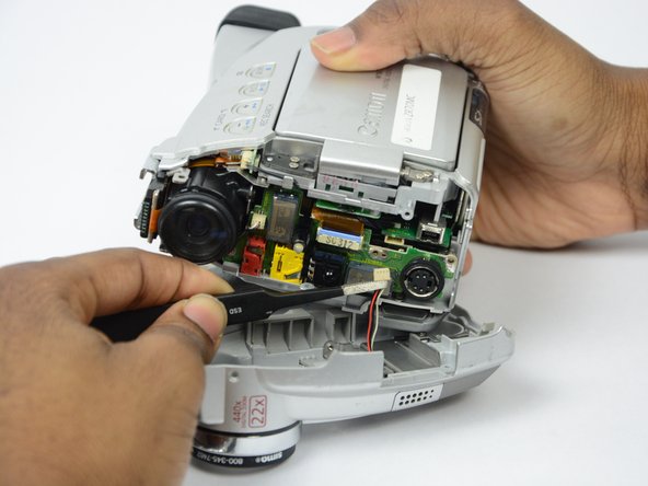
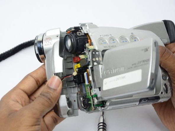
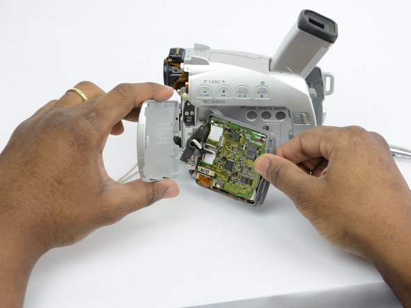
Now that all of the screws are removed, remove the front panel by gently pulling on the front panel.
-
-
Questo passaggio è privo di traduzione. Aiuta a tradurlo
-
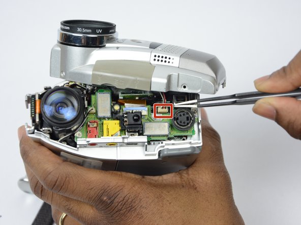
Use tweezers to gently pull the speaker wire from the main body of the camcorder.
-
Pull the front panel completely away from the main body of the camcorder.
-
-
Questo passaggio è privo di traduzione. Aiuta a tradurlo
-
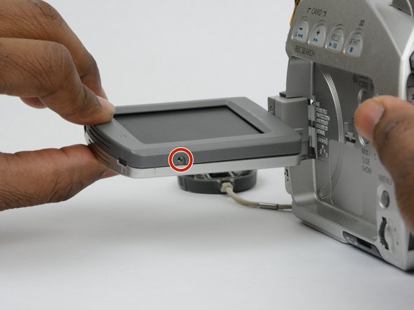
Open the LCD screen.
-
Locate and remove the 2.7 mm screw on the bottom of the LCD monitor.
-
-
Questo passaggio è privo di traduzione. Aiuta a tradurlo
-
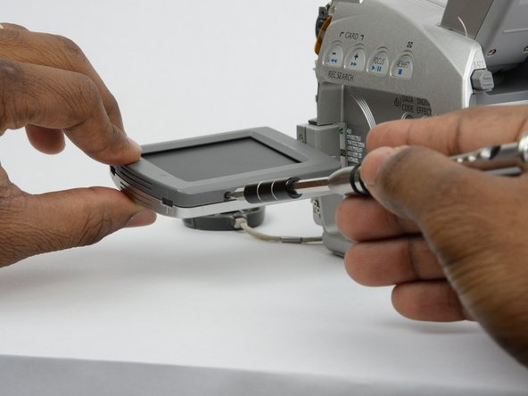
Turn the LCD monitor so that the screen is facing down.
-
There is a 2.7 mm screw on the LCD monitor where the monitor is connected to the main body of the camcorder. Remove the 2.7 mm screw.
-
-
Questo passaggio è privo di traduzione. Aiuta a tradurlo
-
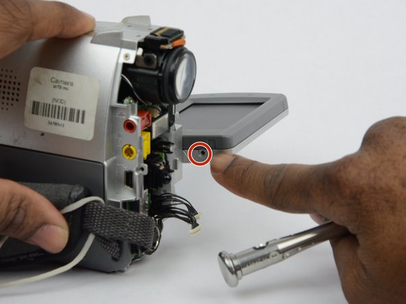
Turn the LCD monitor so that the screen is facing up.
-
There is a 2.7 mm screw located where the LCD monitor is connected to the main body of the camcorder. Remove the 2.7 mm screw.
-
-
Questo passaggio è privo di traduzione. Aiuta a tradurlo
-
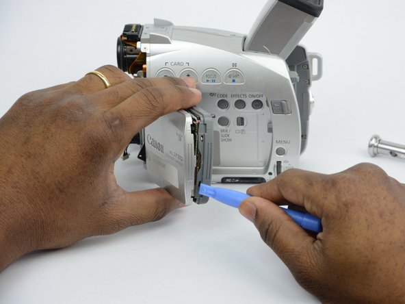
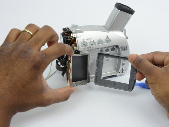
Now that all the screws are removed, use the plastic opening tool to gently pry the LCD monitor case open.
-
-
Questo passaggio è privo di traduzione. Aiuta a tradurlo
-
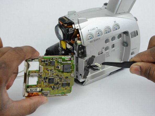
Use tweezers to remove the wire connections that hold the LCD screen in place.
-
Remove the entire LCD screen.
-


Annulla: non ho completato questa guida.
Un'altra persona ha completato questa guida.
Team

USF Tampa, Team S13-G2, Boczar Fall 2017 Membro di USF Tampa, Team S13-G2, Boczar Fall 2017
USFT-BOCZAR-F17S13G2
3 Membri
14 Guide realizzate