Questa versione può contenere modifiche errate. Passa all'ultima istantanea verificata.
Cosa ti serve
-
Questo passaggio è privo di traduzione. Aiuta a tradurlo
-
Remove the 8 Phillips screws from the back of the speaker.
-
-
Questo passaggio è privo di traduzione. Aiuta a tradurlo
-
Carefully remove the back panel, lifting out the metal electronics-box with it.
-
-
Questo passaggio è privo di traduzione. Aiuta a tradurlo
-
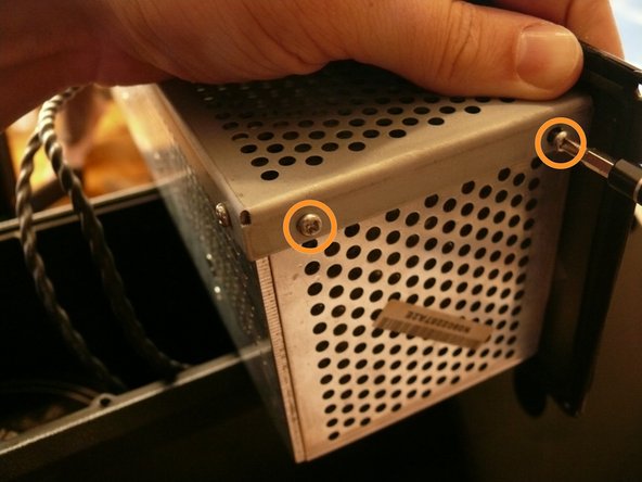
There are two silver, 6 mm-long machine screws with two 1/8" inner-diameter washers on the exterior of the metal electronics box; remove these first using a #2 philips screwdriver.
-
There are five of the same type of machine screw (silver, 6 mm-long) remaining around the metal electronics box's exterior; remove these as well.
-
-
Questo passaggio è privo di traduzione. Aiuta a tradurlo
-
Remove the portion of the metal housing that you freed with the 7 screws in the previous step.
-
-
Questo passaggio è privo di traduzione. Aiuta a tradurlo
-
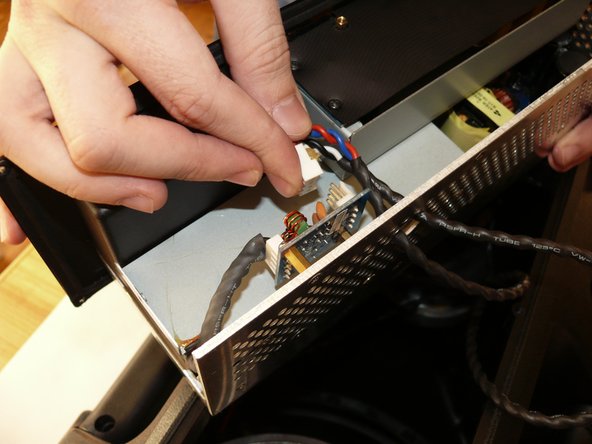
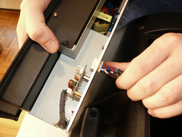
Inside the metal electronics box housing is a white clip attached to a small PCB; remove this.
-
Snake the clip head through the hole in the metal electronics box casing.
-
-
-
Questo passaggio è privo di traduzione. Aiuta a tradurlo
-
Remove the 4, 7/32" long machine screws with a #2 phillips head screwdriver.
-
-
Questo passaggio è privo di traduzione. Aiuta a tradurlo
-
Rotate the back panel so you can view the interior; note the three wires attached.
-
Remove the wires to you can fully remove the back panel.
-
-
Questo passaggio è privo di traduzione. Aiuta a tradurlo
-
Remove the 4 indicated 9/32" long screws with the #1 phillips head screwdriver
-
-
Questo passaggio è privo di traduzione. Aiuta a tradurlo
-
Remove all three of the knobs by pulling them straight up.
-
-
Questo passaggio è privo di traduzione. Aiuta a tradurlo
-
Remove the 4 indicated 9/32" long screws using a #1 phillips head screwdriver.
-
-
Questo passaggio è privo di traduzione. Aiuta a tradurlo
-
Remove the 2 indicated 3/16" long machine screws with a #1 phillips head screwdriver.
-
-
Questo passaggio è privo di traduzione. Aiuta a tradurlo
-
The control PCB is free now, ready to be removed from the speaker's back panel.
-


Annulla: non ho completato questa guida.
Altre 4 persone hanno completato questa guida.
5 Commenti
In Step 3 there are 2 more screws, along the side of the 'electronics box’.
The washer and nut securing the 1/4” socket also need to be removed.
Hi,i like to conect the board to another amp pcb but i dont now wich cable is for what ,do you now where is the power and the inputs?i already look for schematics but i didnt find anything about..thanx
Where do I find a replacement control PCB for my B212A??
Hi
My Behringer Eurolive B215D speaker has got a serious hissing sound when I plug just the power with no audio player connected. Anyone with any idea what can course this? Thanks.