Questa versione può contenere modifiche errate. Passa all'ultima istantanea verificata.
Cosa ti serve
-
Questo passaggio è privo di traduzione. Aiuta a tradurlo
-
Move the battery catch to the "unlocked" position.
-
Pull back the second spring-loaded battery catch until the battery pops up.
-
Remove the battery.
-
-
Questo passaggio è privo di traduzione. Aiuta a tradurlo
-
Turn the notebook around to face you.
-
There are two Phillips #00 screws securing the cover panel to the rest of the notebook. Remove these screws.
-
-
Questo passaggio è privo di traduzione. Aiuta a tradurlo
-
Use a spudger to release the panel from the plastic retaining clips keeping it in place.
-
Remove the panel and set it aside.
-
-
Questo passaggio è privo di traduzione. Aiuta a tradurlo
-
The RAM is protected by a transparent cellophane cover.
-
Lift this cover away from the RAM. It will not come free from the RAM.
-
-
Questo passaggio è privo di traduzione. Aiuta a tradurlo
-
Pull back the retaining clips either side of the RAM.
-
It will spring up, ready to be removed.
-
-
Questo passaggio è privo di traduzione. Aiuta a tradurlo
-
Hold on to opposite edges of the RAM chip and gently pull it diagonally upwards to remove it from the computer.
-
Repeat steps 5 and 6 for the second RAM chip if necessary.
-
-
Questo passaggio è privo di traduzione. Aiuta a tradurlo
-
When reinserting RAM, push it diagonally downwards until almost all of the gold connector strip is inside the socket.
-
Push gently down on the RAM until the retaining clips click back over it.
-
-
Questo passaggio è privo di traduzione. Aiuta a tradurlo
-
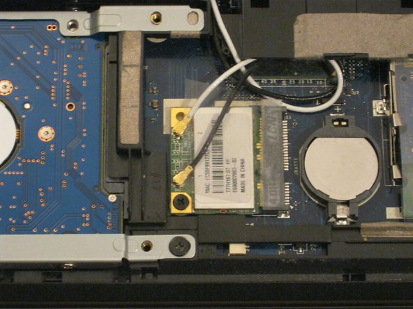
The WLAN card is protected by a transparent cellophane cover.
-
Lift this cover away from the WLAN card. It will not come free from the WLAN card socket.
-
-
-
Questo passaggio è privo di traduzione. Aiuta a tradurlo
-
Use the pointy end of a spudger to remove the antenna connectors from the WLAN card.
-
-
Questo passaggio è privo di traduzione. Aiuta a tradurlo
-
There is one Phillips #00 screw keeping the WLAN card attached to the notebook.
-
Remove this screw.
-
The WLAN card will spring up from the notebook at an angle.
-
-
Questo passaggio è privo di traduzione. Aiuta a tradurlo
-
Just like RAM, hold the WLAN card by the edges and pull it out at an angle.
-
-
Questo passaggio è privo di traduzione. Aiuta a tradurlo
-
You might also want to put the antenna cables back in using the flat end of a spudger.
-
-
Questo passaggio è privo di traduzione. Aiuta a tradurlo
-
Unscrew the Phillips #00 screw which retains the hard drive in place.
-
Gently slide the hard drive to the left in order to disengage the SATA connectors.
-
Lift the drive out of the notebook.
-
-
Questo passaggio è privo di traduzione. Aiuta a tradurlo
-
Unfold the laptop so that you are looking at the keyboard.
-
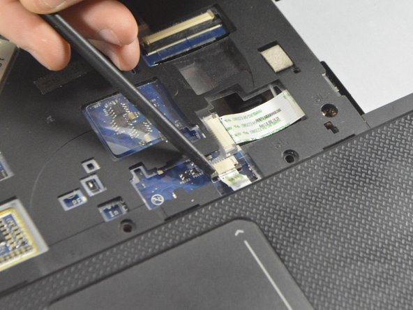
At the top right of the keyboard you will notice two clips above the 'Del' and 'End' keys.
-
Using your spudger, press these clips in to unlock the keyboard from the laptop
-
Slide the spudger along the top of the keyboard until the keyboard is able to easily be lifted up out of the laptop
-
-
Questo passaggio è privo di traduzione. Aiuta a tradurlo
-
To detach this cable you must use the pointed edge of the spudger to press down on the locking mechanisms on each side.
-
After unlocking both sides of the ZIF connector remove the keyboard for replacement.
-
-
Questo passaggio è privo di traduzione. Aiuta a tradurlo
-
Remove the 10 Phillips #0 screws on the bottom cover.
-
Remove the 4 Phillips #00 screws from under the battery.
-
-
Questo passaggio è privo di traduzione. Aiuta a tradurlo
-
Remove the 8 Phillips #0 screws from under the keyboard.
-
-
Questo passaggio è privo di traduzione. Aiuta a tradurlo
-
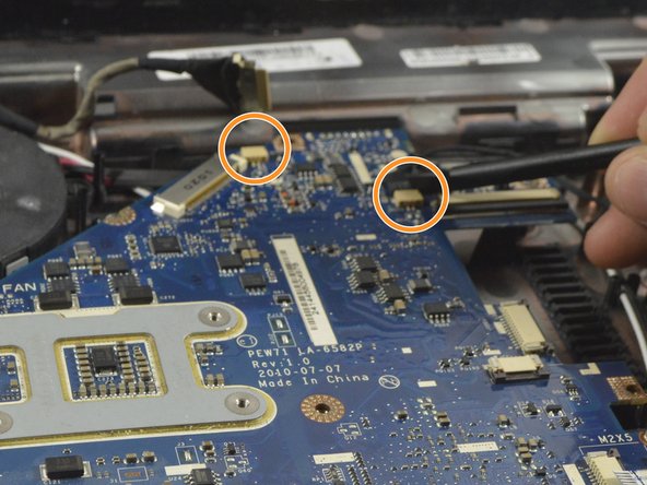
Release the two ribbon cables from the ZIF connectors in the same fashion as in Step 11 with the black spudger.
-
Once the mechanism is released you may remove the cable by hand.
-
The plastic cover can now be easily lifted and removed from the rest of the laptop.
-
-
Questo passaggio è privo di traduzione. Aiuta a tradurlo
-
Remove the two remaining ribbon cables as described in Step 11.
-
-
Questo passaggio è privo di traduzione. Aiuta a tradurlo
-
Remove the display cable with the spudger by pushing each end of the cable out of the connector until it is loose enough to be pulled out by hand.
-
In a similar fashion as with the display cable use the spudger to remove the two power cables from the motherboard.
-
-
Questo passaggio è privo di traduzione. Aiuta a tradurlo
-
Remove the 3 Phillips #0 screws from the fan bracket.
-
Lift the fan up and place it back down above the heatsink.
-
The motherboard can be lifted from the side and and then to the right to free the I/O port from the enclosure. Some force may be required to release the heatsink.
-
-
Questo passaggio è privo di traduzione. Aiuta a tradurlo
-
Rotate the motherboard to the right and lay it down so that the copper heatsink is facing up and parallel with the bottom of the monitor.
-
In this position the last cable to the motherboard can be disconnected using the spudger to push each end out until loose enough to pull the cable completely out.
-
The motherboard can now be completely removed from the laptop enclosure.
-
-
Questo passaggio è privo di traduzione. Aiuta a tradurlo
-
Note how the cables leading into each of the hinges are routed, then release them from their guides.
-
Whilst supporting the lid, remove 2 screws from each hinge. You will now be able to lift the lid assemble away from the body.
-


Team
