Cosa ti serve
-
-
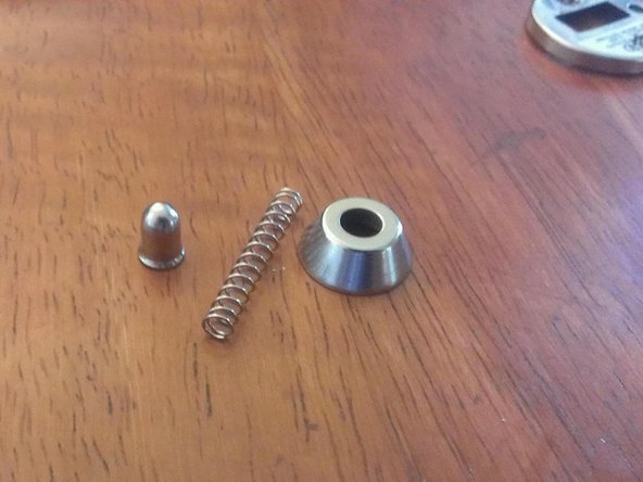
Here we see the device. It is predominately cheap plastic and thin stamped metal.
-
It looks and feels very light and cheap, not a good sign. Though as they say don't judge a book by its cover.
-
-
-
-
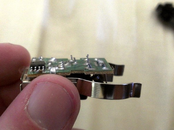
Lets look at the other side. Holy Long Leads Bat Man! Those leads (in the red box) are WAY too long. Compare their length to the ones on the USB connector (in blue). While the soldering looks OK, the long leads show a general lack of attention to detail and cutting of costs.
-
Now we get a good look at the circuit board in general. The more signs of cost cutting. The solder mask (the stuff that makes the PCB green) has huge empty spaces around the solder pads. You can clearly see the brown PCB through there. This increases the risks of short circuits etc. Once again cheap design.
-
The main IC seems to be an MC34063 switching regulator. A veritable workhorse in USB chargers. While this IC can drive up to 1.5A it is only considered good for up to 700mA continuous before heat becomes an issue. Uh oh.
-
-
-
Here we see the stock schematic from the database.
-
In the next image we see the schematic used in the device. We see many values have changed.
-
The biggest change is that Rsc is 0.22ohms. This gives an Ipk of 1.36A, which gives an Iout Max of 0.68A. This is FAR from the quoted 1A.
-
Also, the input and output capacitors have been reduced in size to 10uF and 100uF respectively. This means that we will see MUCH larger ripple on the output. Possibly falling out of USB spec and putting the attached device at risk.
-
Quite simply, the device is a rebadged 500mA or 750mA USB charger at best. It is NOT 1A capable, despite what the sticker on the body says.
-


11 Commenti
I tore down the same device with much the same comments - http://mm0hai.net/blog/2012/08/01/Messag...
Could you do a tear down of the more advanced usb car chargers, it would be interesting on how these are made and work
The right conclusion of R(3.6K) it has to be connected to the right conclusion of L (220uH).
I have already ordered a charger from the best seller of Amazon
Looking at the pic in step 6, it would appear the two data pins are shorted together, tied to +5V via a 75k-ohm resistor, and tied to ground via a 45k-ohm resistor. The resultant voltage divider should hold the two data pins at about +2V. As the data pins have 0V between them, any remotely modern cell phone will recognize this as a charger. An Apple device would recognize this as a 500ma charger, and most recent Android devices mimic Apple's scheme for identifying chargers.
The de-rated capacitors were likely deemed sufficient to regulate the ripple at 500ma. Such cost-cutting (and exaggerated specs) is par for the course with products manufactured and designed in China. My experience is that these things reliably (but slowly) charge my iPhone, and I can get them at the Dollar Tree.
It's been my experience these things work reliably with my Apple devices,
Just did some load testing with one of these, probably good for 500mA. At .55A over time the voltage will still drop out. I've seen chargers that use the MC34063 put out an amp easy. This one could if they did a good job with it, but they cheaped out. It's pretty much garbage for most applications.
Edit: Just took it apart, it this one is designed with another chip, The AD84064. Looks like a it's probably a cheaper alternative, and a worse performer.
The schematic doesn't show the LED. I would like to know if it can be removed without affecting the operation. I don't need it, don't want it, and it just consumes power.
I think it is driven off of the 12V line with a resistor. You should be just fine to remove it.
PedroDaGr8 I am building a cigarette lighter device with some proprietary functionality. I would love to get your input on this project. please reach out to me at txwinder@gmail.com