Salta al contenuto principale

Cosa ti serve

Questo smontaggio non è una guida di riparazione. Per riparare il tuo Game Boy, usa il nostro manuale di assistenza.

  1. Game Boy Teardown, Game Boy Teardown: passo 1, immagine 1 di 2 Game Boy Teardown, Game Boy Teardown: passo 1, immagine 2 di 2
    • The Nintendo Game Boy was initially released in Japan on April 21, 1989, followed by a launch in North America three months later on July 31, and in Europe over a year later. This would be the start of a handheld gaming revolution.

    • Tech Specs:

    • 4.19 MHz 8-bit processor

    • 8 KB of RAM

    • 2.6" 160x144 LCD display

  2. Game Boy Teardown: passo 2, immagine 1 di 3 Game Boy Teardown: passo 2, immagine 2 di 3 Game Boy Teardown: passo 2, immagine 3 di 3
    • Denoted by model number DMG-01 (which stands for Dot Matrix Game), the Game Boy can be powered by either four AA batteries or an AC power adapter, the latter of which has unsurprisingly disappeared somewhere into the clutter abyss.

    • Despite the one model number, the Game Boy came in a handful of different models over the years with subtle differences to the circuitry.

    • If you're wondering, that 800 number does still call Nintendo's support line, just in case you ever need some help with your retro handheld.

  3. Game Boy Teardown: passo 3, immagine 1 di 2 Game Boy Teardown: passo 3, immagine 2 di 2
    Attrezzo utilizzato in questo passaggio:
    Mako Driver Kit - 64 Precision Bits
    $39.95
    Compra
    • The case is held together by six tri-point Y1 screws. Even back in 1989, Nintendo thought traditional screws might be too easy for us tinkerers. Fortunately, our Mako Driver Kit comes with the necessary bit.

    • Nintendo was at least nice enough to include an indentation for our driver to nicely fit into within the battery compartment.

  4. Game Boy Teardown: passo 4, immagine 1 di 3 Game Boy Teardown: passo 4, immagine 2 di 3 Game Boy Teardown: passo 4, immagine 3 di 3
    • We slowly separate the two halves of the outer shell to reveal a ribbon cable booby trap! Luckily, this ribbon cable is way more difficult to damage than those you'll find in newer devices.

    • A firm grab and pull of the ribbon cable is all that stands between complete front and back separation.

  5. Game Boy Teardown: passo 5, immagine 1 di 1
    • Once we're inside, it's all standard Phillips #1 screws from here on out. The display's circuit board is held down with ten of them.

  6. Game Boy Teardown: passo 6, immagine 1 di 3 Game Boy Teardown: passo 6, immagine 2 di 3 Game Boy Teardown: passo 6, immagine 3 di 3
    Attrezzo utilizzato in questo passaggio:
    iFixit Opening Tool
    $1.99
    Compra
    • Using an Opening Tool, we slowly start prying from the top, as the display and circuit board are ever-so-slightly glued to the case.

  7. Game Boy Teardown: passo 7, immagine 1 di 3 Game Boy Teardown: passo 7, immagine 2 di 3 Game Boy Teardown: passo 7, immagine 3 di 3
    • The LCD display is attached to the circuit board with clips and couple of screws. Unfortunately, the display's cable is soldered to the board.

    • The speaker's two wires are also soldered to the circuit board.

  8. Game Boy Teardown: passo 8, immagine 1 di 3 Game Boy Teardown: passo 8, immagine 2 di 3 Game Boy Teardown: passo 8, immagine 3 di 3
    • The circuit boards inside the rear case are much easier to remove, with only four screws and no adhesive holding it down!

    • The mainboard, power board, and jack board are connected together and come out all at once.

    • As with the display and speaker wires, the headphone jack and other ports are all soldered to the boards.

  9. Game Boy Teardown: passo 9, immagine 1 di 1
    • Enhance! Here's what's on the main board of our specific model:

    • Sharp LR35902 4.19 Mhz CPU

    • LSI Logic LH5264N4T 8 KB VRAM

    • LSI Logic LH5264N4T 8 KB WRAM

    • Sharp IR3R40 amplifier

  10. Game Boy Teardown: passo 10, immagine 1 di 1
    • We hope you enjoyed this trip down memory lane!

    • Now if you'll excuse us, we're going to put this thing back together and enjoy some Super Mario Land 2.

Craig Lloyd

Membro da: 02/10/16

35.354 Reputazione

82 Guide realizzate

8 Commenti

We truly have come a long way =) Thanks for the share.

Justin Adams - Replica

2020. Thanks

kajajosavic - Replica

Great tear down, thank you for highlighting the chips.

Jacob Shepard - Replica

Great tear down! I want to use an old gameboy to frame it like this:

https://images.squarespace-cdn.com/conte...

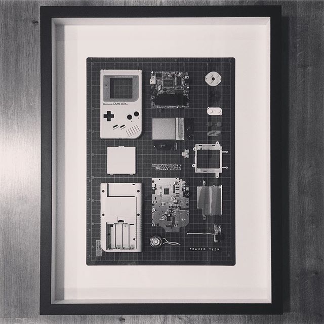
Regarding Step 7, it says here: “The LCD display is attached to the circuit board with clips and couple of screws. Unfortunately, the display's cable is soldered to the board.”

My question: what’s the best and cleanest way to remove the LCD display? It doesn’t have to function again afterwards, it just needs to look as nice and cleanly taken apart as possible :)

If anyone has a good hint, please let me know! Thanks!

Konradin Resa - Replica

Fanning a soldering iron back and forth on the soldered connection should do the trick!

Craig Lloyd -

Aggiungi Commento

Visualizza Statistiche:

Ultime 24 Ore: 18

Ultimi 7 Giorni: 234

Ultimi 30 Giorni: 877

Tutti i Tempi: 42,383