Questa versione può contenere modifiche errate. Passa all'ultima istantanea verificata.
Cosa ti serve
-
-
Utilizza una moneta per ruotare la vite che blocca la batteria di 90 gradi in senso orario.
-
Estrai la batteria dal computer.
-
-
-
Tira le alette di rilascio della tastiera (evidenziate in rosso) verso di te e solleva la tastiera finché non viene fuori.
-
Se la tastiera non viene fuori, utilizza un piccolo cacciavite a taglio per ruotare la vite che blocca la tastiera di 180 gradi in qualsiasi direzione e riprova.
-
Capovolgi la tastiera, lontana dallo schermo, e posizionala a testa in giù sull'area del trackpad.
-
-
-
Utilizza uno spillo per rimuovere i tre piedini in gomma dal case inferiore.
-
-
-
Passa uno spudger lungo la linea di giunzione tra il case inferiore e il case superiore sulla parte anteriore del computer per liberare le alette che bloccano il case inferiore.
-
Tira su sul case inferiore e continua a utilizzare uno spudger finché necessario fino a sentire tre click distinti.
-
-
-
Questo passaggio è privo di traduzione. Aiuta a tradurlo
-
Remove the following 9 screws on the bottom of the computer:
-
Three 3 mm Phillips around the battery compartment.
-
Three 5 mm Phillips on the left and bottom edges.
-
Three 14.5 mm Phillips on the top and right edges (you may have to peel back the foil tape to reveal the screw near the security lock slot).
-
-
Questo passaggio è privo di traduzione. Aiuta a tradurlo
-
Turn over the computer and open it.
-
Pry up the magnet covering a Phillips screw near the middle of the computer.
-
-
Questo passaggio è privo di traduzione. Aiuta a tradurlo
-
Remove the following 3 screws on the edges of the keyboard area:
-
Two 6 mm Phillips underneath the keyboard area.
-
One 9 mm Phillips above the keyboard area.
-
-
Questo passaggio è privo di traduzione. Aiuta a tradurlo
-
With your fingernails, grasp the locking bar on either side and pull up a small amount (about 1/16" or 2 mm).
-
After disengaging the locking bar, slide the cable out of the connector.
-
-
Questo passaggio è privo di traduzione. Aiuta a tradurlo
-
Loosen the trackpad connector by pulling the top piece up slightly, freeing the trackpad ribbon.
-
Slide the orange trackpad ribbon out of the connector.
-
-
Questo passaggio è privo di traduzione. Aiuta a tradurlo
-
Use a straightened paperclip to open the optical drive tray, and pull it out about halfway.
-
-
Questo passaggio è privo di traduzione. Aiuta a tradurlo
-
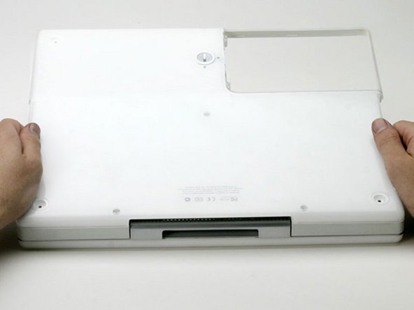
Lift the upper case from the left side and use your other hand to pull out the right side in order to clear the power receptacle.
-
-
Questo passaggio è privo di traduzione. Aiuta a tradurlo
-
Lift the upper case enough to disconnect the blue and white power cable from the logic board.
-
Using your fingernails or a dental pick, carefully pry the connector from its socket.
-
-
Questo passaggio è privo di traduzione. Aiuta a tradurlo
-
Lift the upper case off completely and disconnect the red and black speaker cable from the logic board.
-
-
Questo passaggio è privo di traduzione. Aiuta a tradurlo
-
Remove the following 16 screws:
-
Five 3 mm Phillips (these have smaller heads than the others).
-
Three 5 mm Phillips.
-
Eight 6 mm Phillips.
-
-
Questo passaggio è privo di traduzione. Aiuta a tradurlo
-
Peel back three strips of yellow tape in the bottom, left corner.
-
Peel back one strip of foil tape near the audio-out port, one near where the trackpad connects to the logic board, and one near where the screen latch used to be.
-
-
Questo passaggio è privo di traduzione. Aiuta a tradurlo
-
Lift the top shield up from the right side, minding the upper left corner, which may catch on the metal framework.
-
-
Questo passaggio è privo di traduzione. Aiuta a tradurlo
-
Disconnect the microphone cable from the front, left corner of the logic board.
-
Peel back the black tape and free the microphone cable from the hard drive.
-
-
Questo passaggio è privo di traduzione. Aiuta a tradurlo
-
Use the black plastic handle to disconnect the display data cable from the logic board.
-
-
Questo passaggio è privo di traduzione. Aiuta a tradurlo
-
Remove the two Phillips screws securing the display data cable to the metal framework.
-
-
Questo passaggio è privo di traduzione. Aiuta a tradurlo
-
Deroute the display data and microphone cables, removing tape as necessary.
-
-
Questo passaggio è privo di traduzione. Aiuta a tradurlo
-
Peel back the yellow tape securing the inverter cable to the metal framework.
-
-
Questo passaggio è privo di traduzione. Aiuta a tradurlo
-
Disconnect the inverter cable from the logic board.
-
Carefully deroute the inverter cable from beneath the optical drive.
-
-
Questo passaggio è privo di traduzione. Aiuta a tradurlo
-
Deroute the AirPort antenna cable from beneath the optical drive.
-
-
Questo passaggio è privo di traduzione. Aiuta a tradurlo
-
Remove the single Phillips screw on the outer edge of either hinge (two screws total).
-
Tilt the display back to get over two small nubbins, and then slide it directly from the case and away.
-
-
Questo passaggio è privo di traduzione. Aiuta a tradurlo
-
Use a 1.5 mm hex screwdriver to remove the two hex screws on either side of the display (four screws total).
-
-
Questo passaggio è privo di traduzione. Aiuta a tradurlo
-
Use your thumbs to slightly separate the rear bezel from the front bezel.
-
-
Questo passaggio è privo di traduzione. Aiuta a tradurlo
-
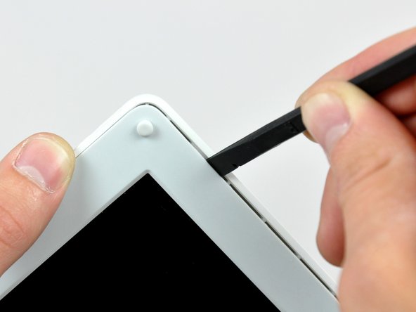
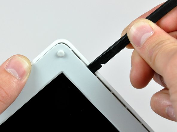
Insert the flat end of a spudger into the gap between the front and rear bezels.
-
Rotate your spudger until it is parallel to the front face of the display.
-
Run the spudger around the perimeter of the display to separate the rear bezel from its retaining clips.
-
-
Questo passaggio è privo di traduzione. Aiuta a tradurlo
-
Remove the pieces of readily removable tape from around the perimeter of the display.
-
Carefully remove the aluminum tape covering the display data cable connection.
-
-
Questo passaggio è privo di traduzione. Aiuta a tradurlo
-
Remove the single screw inserted through the piece of EMI tape near the bottom edge of the display.
-
Use the tip of a spudger to remove the small washer under the screw you just removed.
-
-
Questo passaggio è privo di traduzione. Aiuta a tradurlo
-
Peel the aluminum/EMI tape off the cast aluminum frame of the clutch hinges.
-
-
Questo passaggio è privo di traduzione. Aiuta a tradurlo
-
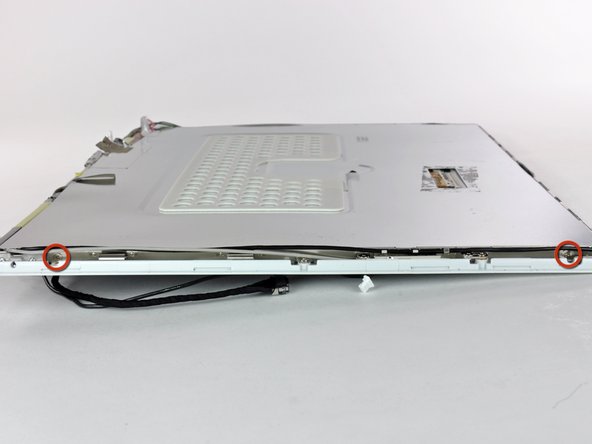
Remove the two Phillips screws securing each side of the LCD to the clutch hinge frame (four screws total).
-
-
Questo passaggio è privo di traduzione. Aiuta a tradurlo
-
Remove the second of the two Phillips screws securing the clutch cover to the cast aluminum frame of the clutch hinges.
-
-
Questo passaggio è privo di traduzione. Aiuta a tradurlo
-
Pull the clutch cover away from the front of the display.
-