Salta al contenuto principale

Questa versione può contenere modifiche errate. Passa all'ultima istantanea verificata.

Cosa ti serve

  1. , Installazione dello sportello di accesso nell'iMac Intel EMC 2133 ed EMC 2210 da 20": passo 1, immagine 1 di 1
    • Allentare la vite con testa a croce al centro dello sportello di accesso.

    • La vite resta all'interno dello sportello di accesso.

    • Rimuovere lo sportello di accesso dall'iMac.

  2. , Installazione del pannello di vetro nell'iMac Intel EMC 2133 ed EMC 2210 da 20": passo 2, immagine 1 di 2 , Installazione del pannello di vetro nell'iMac Intel EMC 2133 ed EMC 2210 da 20": passo 2, immagine 2 di 2
    • Il pannello di vetro è fissato nella mascherina anteriore con quattordici magneti posizionati lungo il perimetro.

    • Far aderire due ventose agli angoli opposti del pannello di vetro.

    • Per far aderire le nostre ventose, per prima cosa posizionarle con la maniglia semovente parallela alla superficie del pannello di vetro. Tenendo delicatamente la ventosa contro il vetro, sollevare la maniglia semovente finché non è parallela all'altra maniglia.

    • Se la ventosa non aderisce, provare a ripulire il pannello di vetro e la ventosa con un solvente delicato, come i detergenti per i vetri.

  3. : passo 3, immagine 1 di 1
    • Estrarre delicatamente il pannello di vetro dall'iMac.

    • Il pannello di vetro presenta diversi piedini di posizionamento lungo il perimetro. Per evitare di staccare i piedini dal pannello di vetro, fare attenzione a rimuoverlo solo tirando verso l'alto.

    • Pulire con attenzione la parte interna del pannello di vetro e l'LCD, poiché la polvere e le impronte digitali saranno sgradevolmente visibili durante l'accensione del display.

  4. , Cornice frontale: passo 4, immagine 1 di 1
    • Rimuovere le 12 viti seguenti, che fissano la mascherina anteriore al case posteriore:

    • Otto viti Torx T8 da 13 mm.

    • Quattro viti Torx T8 da 25 mm.

  5. : passo 5, immagine 1 di 1
    • Metti le mani agli angoli superiori della cornice (di lato) e solleva la cornice a 2-3 cm dal corpo lavorando dall'alto. Dopodiché puoi anche sganciare la parte inferiore della cornice (i moduli di memoria impediranno che la parte inferiore della cornice si stacchi prima). Durante il rimontaggio, inizia con la parte inferiore della cornice.

    • La parte superiore della cornice ospita un microfono collegato alla scheda logica. Solleva delicatamente la cornice per non danneggiare il cablaggio o il connettore del microfono tirando accidentalmente il cavo.

    • A questo punto, puoi staccare il cavo del microfono e rimuovere la cornice, oppure tenere il cavo del microfono attaccato e appoggiare la cornice sul piano di lavoro o sulla scocca del Mac.

    • Per staccare completamente la cornice: scollega il connettore del cavo del microfono, rimuovendo il nastro adesivo se necessario.

    • Per tenerlo collegato, lascia il cavo del microfono collegato alla scheda logica e posiziona la cornice "sopra" la scocca, con il cavo del microfono che forma un cardine.

    • Se tieni il microfono attaccato alla scocca, assicurati di non danneggiare accidentalmente il microfono o la scheda logica urtando la cornice allentata.

  6. : passo 6, immagine 1 di 2 : passo 6, immagine 2 di 2
    • Quando si rimonta la cornice:

    • assicurarsi di infilare il cavo del microfono e il connettore nel foro vicino alla scheda della telecamera.

    • Far passare delicatamente il connettore e i cavi del microfono attraverso lo slot lungo 2-3 cm a destra della telecamera iSight. Una volta che la cornice è stata montata correttamente, spingere delicatamente il connettore del microfono e il cavo nella cornice attraverso quella fessura.

  7. , Pannello Display: passo 7, immagine 1 di 2 , Pannello Display: passo 7, immagine 2 di 2
    • Estrarre il connettore del sensore temperatura dell'LCD direttamente dal connettore sulla scheda logica.

    • Se occorre, deviare il cavo del sensore temperatura dell'LCD dalla parte posteriore della scheda logica.

    • Quando rimuovi il pannello LCD, controlla la disposizione del cavo del controllo temperatura del display. Nel rimontare lo schermo, assicurati che questo cavo non blocchi una delle viti inferiori di fissaggio della cornice anteriore.

  8. : passo 8, immagine 1 di 1
    • Rimuovere le due viti Torx T6 da 5,3 mm che fissano il cavo dati del display alla scheda logica.

  9. : passo 9, immagine 1 di 1
    • Utilizzare la linguetta nera per estrarre il connettore del cavo dati del display dalla scheda logica.

  10. : passo 10, immagine 1 di 2 : passo 10, immagine 2 di 2
    • Rimuovere le otto viti Torx T8 da 12 mm che fissano il pannello del display al case posteriore.

    • A seconda dell'età del tuo driver, una punta Torx T9 potrebbe adattarsi meglio.

    • Sollevare il pannello del display dal bordo sinistro e ruotarlo verso il bordo destro dell'iMac.

  11. : passo 11, immagine 1 di 2 : passo 11, immagine 2 di 2
    • Mentre il pannello del display è sollevato, scollegare i quattro cavi dell'inverter.

    • Durante la reinstallazione, posizionare i quattro connettori dei cavi dell'inverter negli spazi vuoti fra i componenti collegati al pannello posteriore per garantire il corretto allineamento del pannello del display.

    • Durante il riassemblaggio, è possibile inserire i cavi dell'inverter nei rispettivi connettori femmina in qualsiasi ordine.

    • Se devi sostituire il disco fisso e hai un paio di mani supplementari, puoi accedere al disco e rimuoverlo senza scollegare nulla tranne i connettori della temperatura dell'LCD e quella del display come al passo precedente con l'LCD sollevato.

  12. Questo passaggio è privo di traduzione. Aiuta a tradurlo

    : passo 12, immagine 1 di 3 : passo 12, immagine 2 di 3 : passo 12, immagine 3 di 3
    • The rest of this procedure should be done in the cleanest possible work environment to avoid dust getting BEHIND the LCD (I learned this the HARD way!)

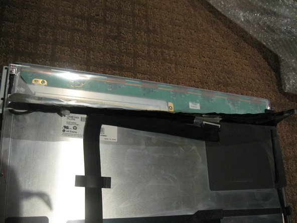
    • Once the LCD panel is removed you need to peel back the black foil from the top edge of the LCD to reveal the clear plastic PCB protector.

    • Now gently peel the clear plastic PCB protector off the top edge. Make sure you don't damage the flex cables attached to the PBC you are exposing.

    • There are a total of 8 flex cables along the top edge

  13. Questo passaggio è privo di traduzione. Aiuta a tradurlo

    : passo 13, immagine 1 di 3 : passo 13, immagine 2 di 3 : passo 13, immagine 3 di 3
    • Use a sharpie or similar, mark the side brackets on either side of the LCD panel before removing screws as they are different

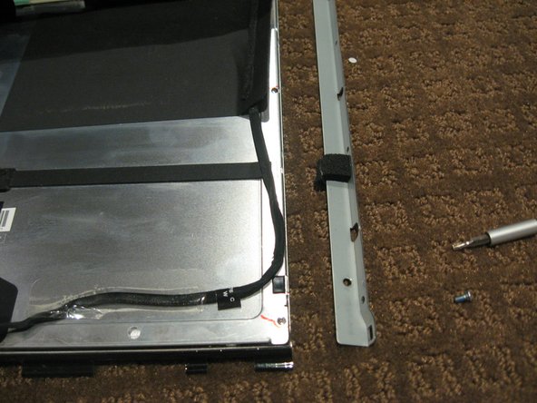
    • Use a T10 Torx driver to remove the 2 screws from each side bracket (total 4 screws)

  14. Questo passaggio è privo di traduzione. Aiuta a tradurlo

    : passo 14, immagine 1 di 3 : passo 14, immagine 2 di 3 : passo 14, immagine 3 di 3
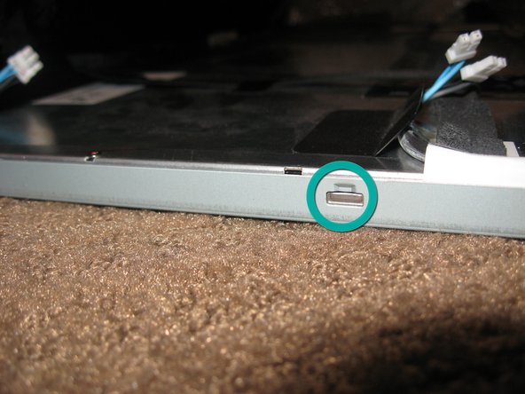
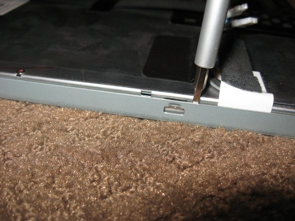
    • Stand the LCD panel on its TOP edge and locate the lock tabs along the BOTTOM edge. There are 5 along the length of the bottom edge

    • Use a flat blade driver or metal spudger to Gently pop the bezel off the lock tabs.

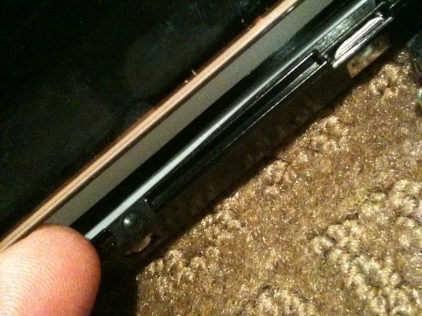
    • Locate the lock tabs on either side of the LCD panel. There are 2 on each side

    • Use a flat blade driver or metal spudger to Gently pop the bezel off the side lock tabs.

  15. Questo passaggio è privo di traduzione. Aiuta a tradurlo

    : passo 15, immagine 1 di 3 : passo 15, immagine 2 di 3 : passo 15, immagine 3 di 3
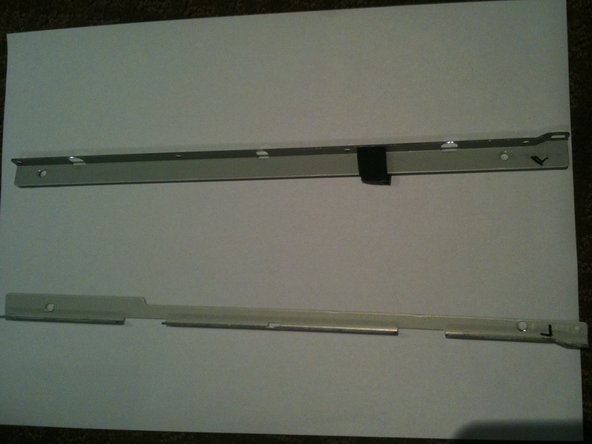
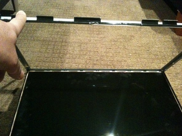
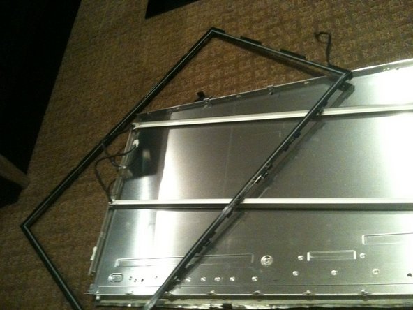
    • Now gently separate the metal bezel from the main body of the LCD panel

    • Lay the LCD panel down on with viewing side UP and remove the metal bezel

    • Make sure you are careful when removing the bezel from the TOP edge as you will be exposing the 8 flex cables mentioned in step 1.

    • Note the 3 flex tabs on the left edge

    • Do not damage any of the tabs or flex cables as these are the Row and Column Drivers. Damage to these will will cause faults like vertical/horizontal lines or white screen etc.

    • WARNING - Once the bezel is removed the LCD is LOOSE in the black plastic frame - only held in by the small gasket underneath.

  16. Questo passaggio è privo di traduzione. Aiuta a tradurlo

    : passo 16, immagine 1 di 2 : passo 16, immagine 2 di 2
    • Using a plastic spudger or pry tool, work GENTLY around the edges of the LCD to loosen it from the gasket below - use GREAT CARE so you don't crack or chip the panel as it is only a couple mm thick

    • Once the LCD is loose you need to HOLD it in place in the black plastic frame and GENTLY flip the entire assembly so the LCD is flat on the work surface

  17. Questo passaggio è privo di traduzione. Aiuta a tradurlo

    : passo 17, immagine 1 di 2 : passo 17, immagine 2 di 2
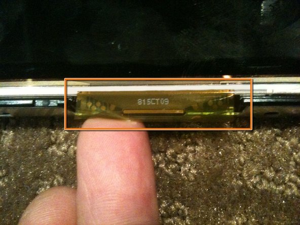
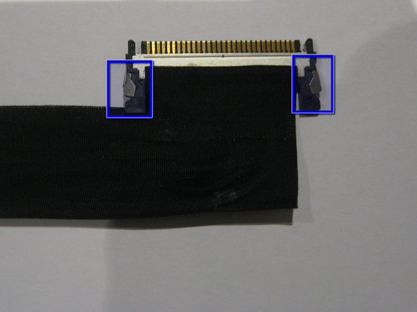
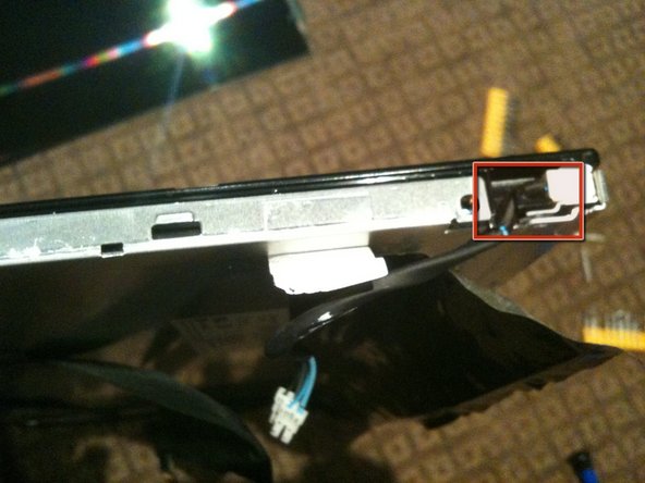
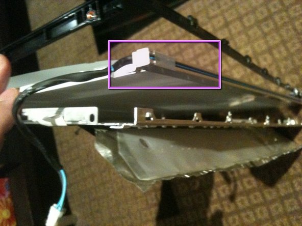
    • Remove the tape securing the LVDS cable

    • Press IN the 2 silver spring loaded catches on either side to release the cable and gently extract it from the connector

  18. Questo passaggio è privo di traduzione. Aiuta a tradurlo

    : passo 18, immagine 1 di 2 : passo 18, immagine 2 di 2
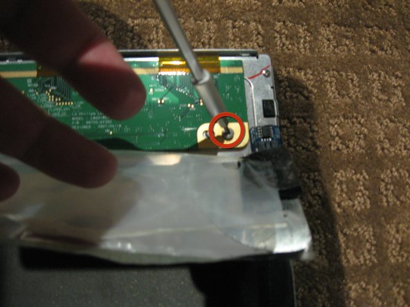
    • Peel the back Black foil and clear plastic PCB protector to fully expose the PCB that runs across the top of the LCD assembly

    • Remove the 2ea Philips head screws from each end of the PCB

    • The PCB actually has a 3rd screw hole in the centre of the board. Perhaps my assembly is missing a screw

  19. Questo passaggio è privo di traduzione. Aiuta a tradurlo

    : passo 19, immagine 1 di 2 : passo 19, immagine 2 di 2
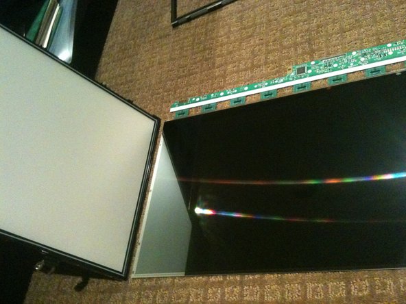
    • Gently flip the PCB over 180deg so it is off the aluminum back panel.

    • Be CAREFUL not to damage the 8 flex cables

    • The PCB may be attached to the aluminium by some adhesive near the LVDS connector. IF so use a plastic pry tool or spudger to GENTLY lift the PCB up

    • Now lift the the back panel off the LCD separating the LCD from the back light assembly

  20. Questo passaggio è privo di traduzione. Aiuta a tradurlo

    : passo 20, immagine 1 di 3 : passo 20, immagine 2 di 3 : passo 20, immagine 3 di 3
    • Disassembling the back-light assembly is a little fiddly as there are a number of parts that all want to come apart at the same time

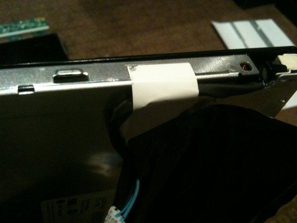
    • Remove the 6 Philips screws from the rear of the back light assembly

    • Removing the white tape from the CCFL cable.

    • Un-clip the CCFL cable from the black plastic surround

    • There are 2 CCFL cables and the process is essentially the same for each

  21. Questo passaggio è privo di traduzione. Aiuta a tradurlo

    : passo 21, immagine 1 di 3 : passo 21, immagine 2 di 3 : passo 21, immagine 3 di 3
    • Separate the black plastic surround from the aluminum back plate to access the CCFL tube assemblies

    • Start by un-clipping the tabs along the top edge of the assembly. There are 4 tabs along the top

    • The top CCFL tube can be seen and CAREFULLY removed

  22. Questo passaggio è privo di traduzione. Aiuta a tradurlo

    : passo 22, immagine 1 di 3 : passo 22, immagine 2 di 3 : passo 22, immagine 3 di 3
    • The bottom of the black surround can now be un-clipped and the entire surround removed

    • There are 4 tabs along the bottom of the assembly

    • Once the black surround is off the rest pretty much comes apart with the bottom CCFL tube being able to be removed in a similar manner to the top

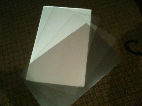
    • The centre of the back light assembly is made up of 4 main parts. A perspex sheet with white plastic coating, 2 opaque matt plastic sheets, and 1 Pearlescent matt plastic sheet

    • The plastic sheets are polarisers so need to be kept clean and free of dust and scratches

  23. Questo passaggio è privo di traduzione. Aiuta a tradurlo

    : passo 23, immagine 1 di 3 : passo 23, immagine 2 di 3 : passo 23, immagine 3 di 3
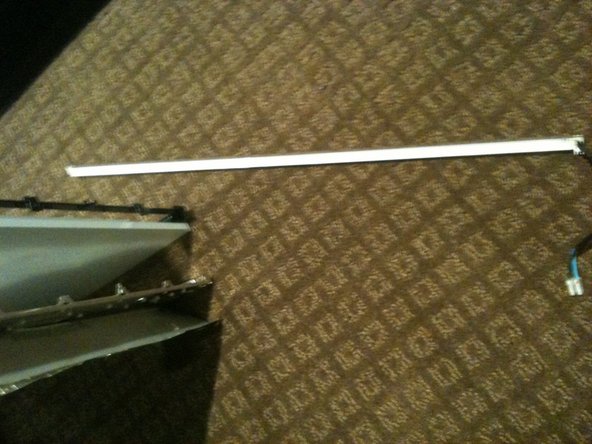
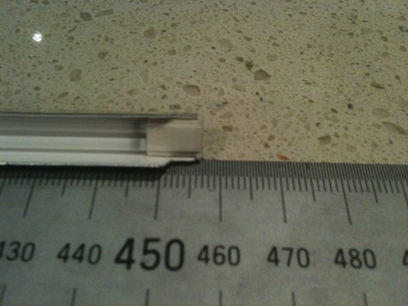
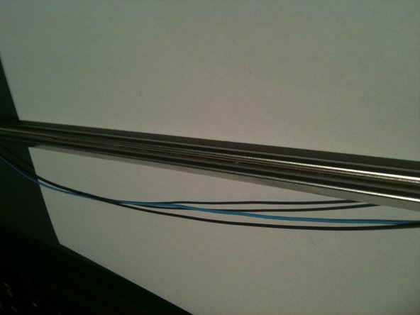
    • The CCLF tube assemblies are made up of a U shaped reflector with 2ea individual tubes inside. The entire assembly is 457mm long and 7.6mm wide. There are no part numbers on the assembly however there is a S on the end with the wires attached and an 18 on the other end.

    • The 2 CCFL tubes are held together with a figure 8 rubber band in the middle of the reflector so both tubes must come out at the same time.

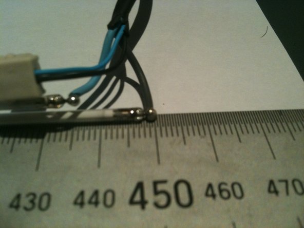
    • The individual tubes are 448mm long (excluding the terminals - standard way to measure is end of glass to end of glass) and are 2.4mm diameter.

    • The CCFL are soldered to the wires so not a simple plug in replacement

    • The CCFL are EXTREMELY fragile so ensure you dont break them when installing them.

    • The CCFL reflectors are a tight fit over the sides of the perspex sheet and the other layers of plastic. Patience and a plastic spudger or pry tool should get you there

    • The closest I can find to my CCFL measurements are either the 446mm x 2.4mm or the 450mm x 2.4mm so I'd suggest the 446mm is used

    • See the Removing CCFL from iMac 20in LCD CCFL assembly guide for details

  24. Questo passaggio è privo di traduzione. Aiuta a tradurlo

    : passo 24, immagine 1 di 3 : passo 24, immagine 2 di 3 : passo 24, immagine 3 di 3
    • Remove the white tape from either end of the rear of the CCFL assembly.

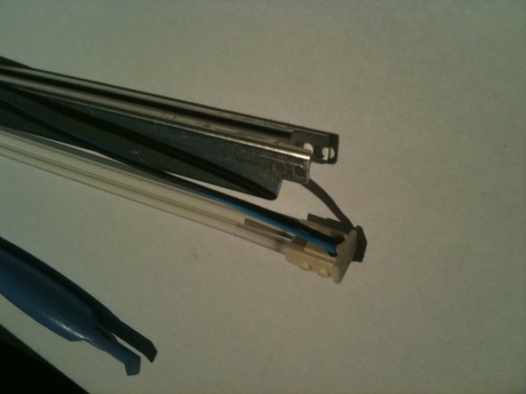
    • Carefully remove about 15-20mm of heat shrink from the CCFL cable to allow the end cap to be removed, making sure you DO NOT cut or nick the wire insulation.

    • The wires have a HIGH VOLTAGE applied during operation and the insulation may break down if damaged causing a short

    • While holding the assembly, slowly and gently pull the THICK wires up and out of the slots in the white rubber cap.

    • Pull the wires one at a time ensuring you don't flex the CCFL and break it.

    • This will reveal the pins and solder joints.

  25. Questo passaggio è privo di traduzione. Aiuta a tradurlo

    : passo 25, immagine 1 di 3 : passo 25, immagine 2 di 3 : passo 25, immagine 3 di 3
    • Gently push the THIN wires through the rubber end cap to create a bit of a loop on the rear of the assembly.

    • Using a plastic pry tool you can pop the rubber end cap out and then lift the thin wires out of the groove in the rear of the CCFL assembly

    • Note the thin wires are held in the groove by a small amount of adhesive.

    • Run the pry tool the length of the assembly and free the wires all the way to the other end cap

    • gently pop the rubber end cap out of the assembly

  26. Questo passaggio è privo di traduzione. Aiuta a tradurlo

    : passo 26, immagine 1 di 3 : passo 26, immagine 2 di 3 : passo 26, immagine 3 di 3
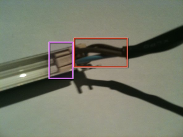
    • Gently pull the rubber end cap off the CCFL to expose the pins and solder joints

    • The CCFL are FRAGILE and will easily break

    • Now its a simple task of un-soldering each wire and soldering in the new CCFL

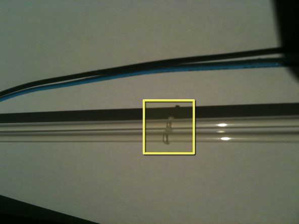
    • There is a little figure 8 rubber band tying the 2 CCFL together at their centre.

Linea Traguardo

Altre 5 persone hanno completato questa guida.

Richdave

Membro da: 04/09/10

32.051 Reputazione

30 Guide realizzate

Team

Master Techs Membro di Master Techs

Community

322 Membri

2.521 Guide realizzate

Un commento

Anyone swapped out the ccfl for leds?

Dan - Replica

Aggiungi Commento

Visualizza Statistiche:

Ultime 24 Ore: 2

Ultimi 7 Giorni: 6

Ultimi 30 Giorni: 18

Tutti i Tempi: 15,816