Questa versione può contenere modifiche errate. Passa all'ultima istantanea verificata.
Cosa ti serve
-
-
Se lo schermo del tuo display è crepato, contieni ulteriori rotture e previeni danni fisici durante la riparazione coprendo lo schermo con del nastro adesivo.
-
Posiziona delle strisce sovrapposte di nastro adesivo da imballaggio sopra al display dell'iPod finché tutto il vetro non sia coperto.
-
-
-
Utilizza un asciugacapelli oppure prepara un iOpener e applicalo al bordo inferiore dell'iPod per circa un minuto al fine di ammorbidire l'adesivo sottostante.
-
La base dello schermo (vicino al pulsante home) è tenuta in posizione con un adesivo potente.
-
Mentre inizi a fare leva per rimuovere lo schermo nei prossimi passi, potresti aver bisogno di applicare più calore per mantenere la colla calda e flessibile.
-
-
-
Tieni con fermezza l'iPod contro un tavolo o una panca.
-
Solleva la ventosa verso l'alto e indietro verso la parte superiore dell'iPod. Sii paziente, e tira con forza costante finché l'adesivo si rompe e il display viene via dal case posteriore.
-
Potrebbe essere necessario utilizzare una pistola termica per ammorbidire l'adesivo (specialmente nei climi più freschi). Se riesci a fare leva e a sollevare lo schermo, ma l'adesivo rimane ancora attaccato e si stacca come il formaggio su una pizza, puoi far scorrere una lametta sottile dentro e tagliare delicatamente l'adesivo.
-
-
-
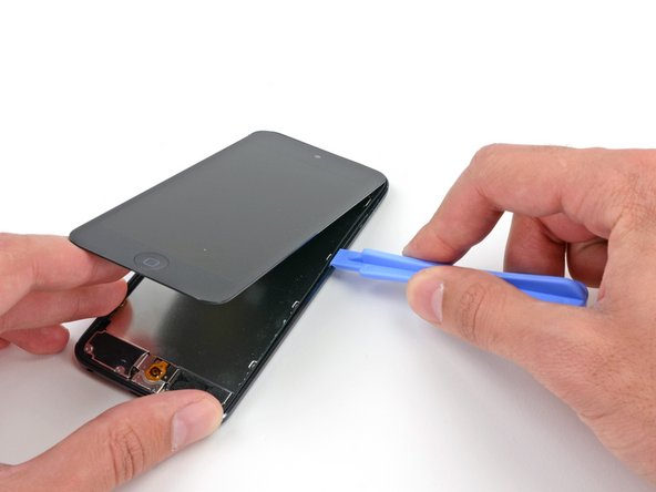
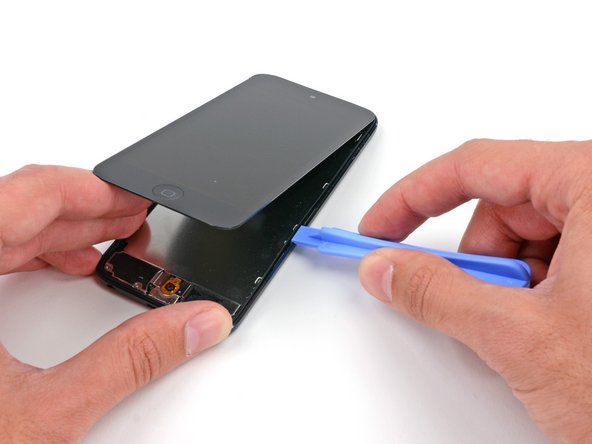
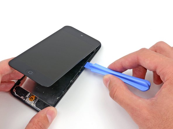
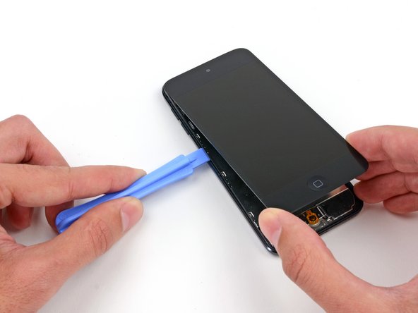
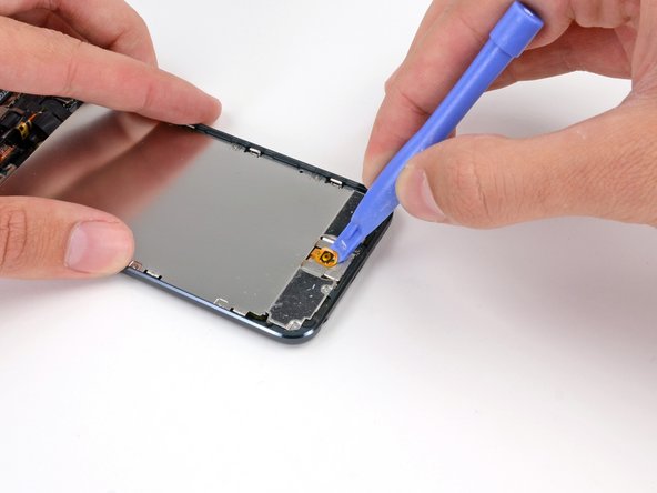
Inserisci uno strumento di apertura in plastica tra il telaio e il case posteriore dietro la prima clip.
-
Muovi lo strumento lateralmente, per allargare lo spazio dietro la clip e separarlo dal case posteriore.
-
Questo potrebbe anche non liberare la clip inizialmente, ma ripetendo la procedura per ciascuna clip questo inizierà a far allentare il pezzo.
-
-
Questo passaggio è privo di traduzione. Aiuta a tradurlo
-
If your iPod has a black home button assembly rather than the orange one shown here, you can skip this step. The button is not attached to the LCD plate and does not need to be removed to complete the repair.
-
Use a plastic opening tool to pry the home button switch up from the LCD plate.
-
It may be necessary to use a heat gun or hair dryer to soften the adhesive on the back of the home button. Always use a low heat setting.
-
-
Questo passaggio è privo di traduzione. Aiuta a tradurlo
-
Remove the following screws securing the LCD plate to the rear case:
-
Two 1.2 mm #000 Phillips screws
-
Nine 1.6 mm #000 Phillips screws
-
One 2.3 mm #000 Phillips screw
-
-
Questo passaggio è privo di traduzione. Aiuta a tradurlo
-
Lift up and remove the LCD plate from the iPod.
-
-
Questo passaggio è privo di traduzione. Aiuta a tradurlo
-
Remove three 1.6 mm #000 Phillips screws securing the logic board to the rear case.
-
-
-
Questo passaggio è privo di traduzione. Aiuta a tradurlo
-
There are two strips of adhesive keeping the battery in place.
-
Turn the iPod over and heat the BACK of the aluminium iPod case. Do not heat the battery.
-
The aluminium case does not have to be hot; you should always be able to touch heated parts with your fingers at all times without it being uncomfortable.
-
-
Questo passaggio è privo di traduzione. Aiuta a tradurlo
-
Insert a plastic opening tool into the top right notch and gently pry up on the battery.
-
-
Questo passaggio è privo di traduzione. Aiuta a tradurlo
-
Continue with the lower right notch. Insert the plastic opening tool into the notch, and gently pry up on the side of the battery.
-
-
Questo passaggio è privo di traduzione. Aiuta a tradurlo
-
Continue prying the battery up from the bottom.
-
-
Questo passaggio è privo di traduzione. Aiuta a tradurlo
-
Once all of the adhesive is loosened, lift the battery up from the bottom and swing it out over the left side of the rear case.
-
Flip the battery over to straighten its cable and set it down.
-
-
Questo passaggio è privo di traduzione. Aiuta a tradurlo
-
Use the flat end of a spudger to flip the front-facing camera out of its socket in the display assembly.
-
-
Questo passaggio è privo di traduzione. Aiuta a tradurlo
-
Use the tip of a spudger to peel back a small piece of tape covering a screw on the left side of the headphone jack.
-
-
Questo passaggio è privo di traduzione. Aiuta a tradurlo
-
Remove the following screws securing the headphone jack, Lightning connector, and speaker.
-
Three 2.6 mm #000 Phillips screws
-
Two 2.0 mm #000 Phillips screws
-
-
Questo passaggio è privo di traduzione. Aiuta a tradurlo
-
Use the flat end of a spudger to pry the speaker up from the rear case.
-
-
Questo passaggio è privo di traduzione. Aiuta a tradurlo
-
Grasping the large ribbon cable, gently pull the Lightning connector assembly out of the bottom of the case.
-
-
Questo passaggio è privo di traduzione. Aiuta a tradurlo
-
Flip the entire assembly over, exposing the back of the logic board.
-
Use a plastic opening tool to disconnect the digitizer cable from the logic board.
-
-
Questo passaggio è privo di traduzione. Aiuta a tradurlo
-
Use a plastic opening tool to disconnect the display cable from its socket in the logic board.
-
-
Questo passaggio è privo di traduzione. Aiuta a tradurlo
-
Flip the Lightning connector/logic board assembly back over to expose the top of the logic board.
-
The display cable is lightly adhered to the top of the logic board.
-
Use the flat end of a spudger to peel the display cable up from the logic board.
-
-
Questo passaggio è privo di traduzione. Aiuta a tradurlo
-
Flip the logic board assembly back over to expose the connectors on the back.
-
Use the edge of a plastic opening tool to gently pry the antenna connector off the back of the logic board.
-
-
Questo passaggio è privo di traduzione. Aiuta a tradurlo
-
Disconnect the button ribbon cable connector from the back of the logic board.
-
-
Questo passaggio è privo di traduzione. Aiuta a tradurlo
-
Use the edge of a plastic opening tool to disconnect the display connector from the back of the logic board.
-
-
Questo passaggio è privo di traduzione. Aiuta a tradurlo
-
Remove the logic board assembly from the rear case of the iPod.
-
-
Questo passaggio è privo di traduzione. Aiuta a tradurlo
-
Insert the flat end of a spudger between the rear-facing camera and its frame.
-
Gently twist the spudger to free the camera.
-
Lift the rear-facing camera up out of its socket, and remove it from the iPod Touch.
-
-
Questo passaggio è privo di traduzione. Aiuta a tradurlo
-
Gently slide the flat end of a spudger underneath the piece of foam tape covering the button ribbon cable.
-
Run the spudger along the full length of the tape to disconnect it from the rear case.
-
-
Questo passaggio è privo di traduzione. Aiuta a tradurlo
-
Peel and remove the foam tape from the rear case of the iPod.
-
-
Questo passaggio è privo di traduzione. Aiuta a tradurlo
-
Use the tip of a spudger to peel up the edge of the tape covering the button ribbon cable.
-
Use tweezers or your fingers to peel the tape up from the rear case, and remove it from the iPod.
-
-
Questo passaggio è privo di traduzione. Aiuta a tradurlo
-
Remove the following screws securing the button ribbon cable to the rear case of the iPod:
-
Two 2.0 mm #000 Phillips screws
-
Two 2.3 mm #000 Phillips screws
-
One 1.6 mm #000 Phillips screw
-
-
Questo passaggio è privo di traduzione. Aiuta a tradurlo
-
Use tweezers to remove the small metal backing plate from the power switch section of the button ribbon cable.
-
-
Questo passaggio è privo di traduzione. Aiuta a tradurlo
-
Insert a plastic opening tool into the rear-facing camera frame and pry up against the rear case.
-
Twist the plastic opening tool slightly counter-clockwise to pry the camera frame up from the rear case.
-
-
Questo passaggio è privo di traduzione. Aiuta a tradurlo
-
Use the closed tip of a pair of tweezers to push the power/sleep button into the rear case.
-
Use tweezers to remove the power button from the iPod.
-
-
Questo passaggio è privo di traduzione. Aiuta a tradurlo
-
Use a plastic opening tool to pry the microphone up from the rear case.
-
-
Questo passaggio è privo di traduzione. Aiuta a tradurlo
-
Slide a plastic opening tool from right to left underneath the horizontal section of the cable, separating it from the adhesive securing it to the rear case.
-
-
Questo passaggio è privo di traduzione. Aiuta a tradurlo
-
Gently peel the rest of the cable up from the rear case.
-
Remove the button ribbon cable from the iPod.
-


Annulla: non ho completato questa guida.
Altre 6 persone hanno completato questa guida.
