Questa versione può contenere modifiche errate. Passa all'ultima istantanea verificata.
Cosa ti serve
-
-
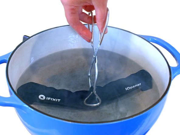
Riempi una pentola o una padella con abbastanza acqua per immergerci un iOpener.
-
Scalda l'acqua finché non bolle. Spegni il fuoco.
-
Posiziona l'iOpener nell'acqua calda per 2-3 minuti. Assicurati che l'iOpener sia completamente immerso nell'acqua.
-
Usa delle pinze per estrarre l'iOpener scaldato dall'acqua calda.
-
Asciuga accuratamente l'iOpener con un asciugamano.
-
Il tuo iOpener è pronto all'uso! Se devi scaldare di nuovo l'iOpener, scalda l'acqua fino all'ebollizione, spegni il fuoco e immergi l'iOpener in acqua per 2-3 minuti.
-
-
-
Se il vetro dello schermo è crepato, previeni ulteriori rotture e danni fisici durante la riparazione coprendo lo schermo con del nastro adesivo trasparente.
-
Sovrapponi strisce di nastro adesivo trasparente per coprire tutta la superficie dello schermo dell´iPad.
-
Fai del tuo meglio per seguire il resto della guida, come descritta. In ogni caso, uno schermo crepato continuerà probabilmente a danneggiarsi durante la riparazione e, perciò potrebbe essere necessario utilizzare uno strumento metallico per estrarre il vetro.
-
-
-
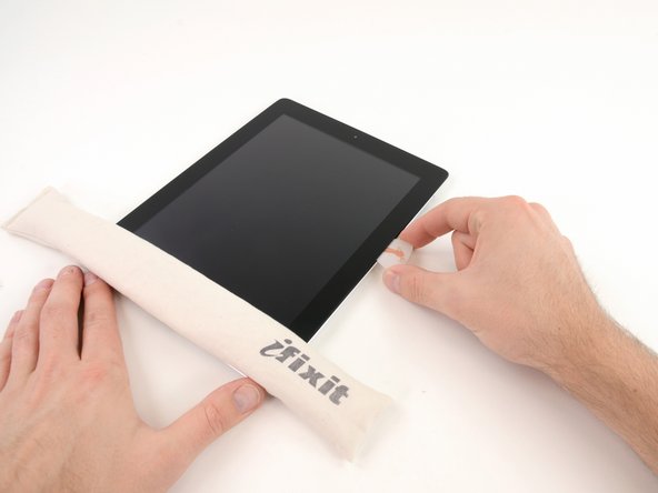
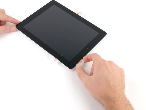
C'è una piccola fessura nell'anello adesivo dell'iPad nell'angolo in alto a destra, a circa 5 cm dal bordo superiore. Dovrai sfruttare questa debolezza.
-
Allinea lo strumento con il tasto del muto. Infila la punta di uno uno strumento di apertura in plastica nella fessura tra il vetro anteriore e il bordo in plastica. Infila solo la punta dello strumento, solo abbastanza per allargarla.
-
-
-
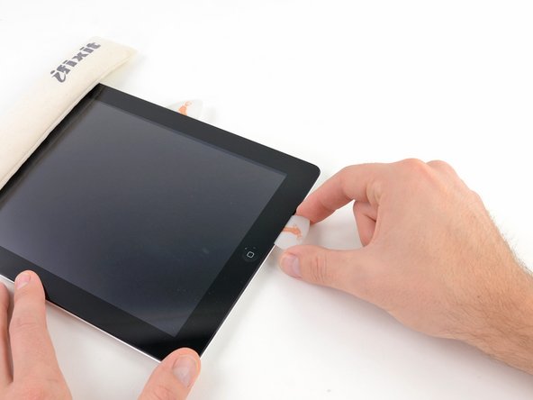
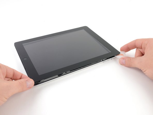
Una volta superata l'antenna WiFi (a circa da 75 mm dal bordo destro, o accanto al tasto Home), reinfila il plettro completamente.
-
Fai scorrere il plettro verso destra, rilasciando l'adesivo che fissa l'antenna WiFi al vetro anteriore.
-
L'antenna del WiFi è attaccata al bordo inferiore dell'iPad tramite delle viti e un cavo. Questo passaggio separa l'antenna dal pannello anteriore, assicurando che quando lo rimuoverai l'antenna non verrà danneggiata.
-
-
-
-
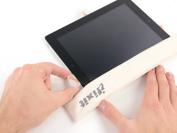
Fai scorrere il plettro sotto il bordo superiore dell'iPad, sfilandolo leggermente per aggirare la staffa della fotocamera anteriore.
-
L'adesivo in questa zona è molto spesso e può essere richiesta abbastanza forza. Lavora attentamente e lentamente, assicurandoti di non scivolare e danneggiare te stesso o l'iPad.
-
-
Questo passaggio è privo di traduzione. Aiuta a tradurlo
-
Remove the four 2.0 mm Phillips screws securing the LCD to the rear case.
-
-
Questo passaggio è privo di traduzione. Aiuta a tradurlo
-
Lift the LCD from its long edge closest to the volume buttons and rotate it out of the rear case.
-
Lay the LCD on the front panel as seen in the second picture.
-
-
Questo passaggio è privo di traduzione. Aiuta a tradurlo
-
Carefully peel the rubber cover off the metal camera retainer and remove it from the iPad 2.
-
-
Questo passaggio è privo di traduzione. Aiuta a tradurlo
-
Remove the following two screws:
-
One 3.3 mm Phillips screw
-
One 2.1 mm Phillips screw
-
Lift the metal retainer clip straight up from its recess in the rear panel.
-
-
Questo passaggio è privo di traduzione. Aiuta a tradurlo
-
Use a plastic opening tool to pry the rear camera connector up from its socket on the upper component board.
-
Remove the rear camera.
-
-
Questo passaggio è privo di traduzione. Aiuta a tradurlo
-
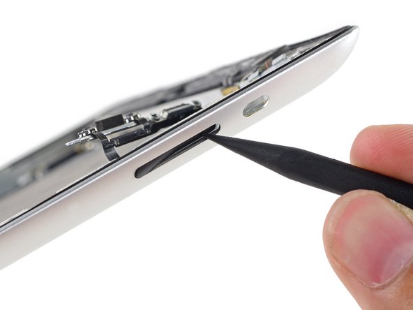
Use the tip of a spudger to flip the retaining tab on the ZIF connector to release the GPS cable.
-
-
Questo passaggio è privo di traduzione. Aiuta a tradurlo
-
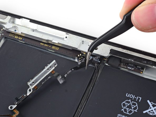
Remove the following screws from the volume/power button assembly cable:
-
Two 2.5 mm Phillips #000 screws, at a 45º angle securing the power button.
-
Two 5 mm Phillips #000 screws
-
One 2 mm Phillips #000 screw at a 45º angle.
-
-
Questo passaggio è privo di traduzione. Aiuta a tradurlo
-
Remove the metal bracket securing the rotation lock/silent switch.
-
-
Questo passaggio è privo di traduzione. Aiuta a tradurlo
-
Pull the power button cable out of the recess in the rear case and bend it out of the way.
-
-
Questo passaggio è privo di traduzione. Aiuta a tradurlo
-
Remove the sleep/power button form the rear case.
-
-
Questo passaggio è privo di traduzione. Aiuta a tradurlo
-
Use the center screw hole of the volume control bracket to tilt it out toward the edge of the case and then pull it up out of its recess.
-
-
Questo passaggio è privo di traduzione. Aiuta a tradurlo
-
Gently peel the power and volume button cable away from the rear case.
-
Bend the cable toward the inside of the rear case, but do not attempt to remove it as it is still connected to the upper component board.
-
-
Questo passaggio è privo di traduzione. Aiuta a tradurlo
-
Remove the rotation lock/silent switch from the rear case.
-
-
Questo passaggio è privo di traduzione. Aiuta a tradurlo
-
Use the tip of a spudger to push the volume rocker into the interior of the rear case.
-
Remove the volume rocker from the rear case.
-
-
Questo passaggio è privo di traduzione. Aiuta a tradurlo
-
Use the point of an opening pick to gently peel the Smart Cover sleep/wake sensor up off the rear case.
-
-
Questo passaggio è privo di traduzione. Aiuta a tradurlo
-
Carefully peel the volume rocker portion of the button cable away from the rear case.
-
-
Questo passaggio è privo di traduzione. Aiuta a tradurlo
-
Gently peel the last horizontal portion off of the rear case.
-
-
Questo passaggio è privo di traduzione. Aiuta a tradurlo
-
Remove the single 2 mm Phillips #000 screw from the lower end of the upper component board.
-
-
Questo passaggio è privo di traduzione. Aiuta a tradurlo
-
Use a set of tweezers to remove the foam block from between the rear case and the upper component board.
-
-
Questo passaggio è privo di traduzione. Aiuta a tradurlo
-
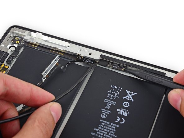
Insert a spudger under the end of the upper component board and gently slide it toward the volume rocker to free the board from adhesive.
-
-
Questo passaggio è privo di traduzione. Aiuta a tradurlo
-
Insert a spudger under the GPS connector end of the upper component board and lift it up off of its adhesive.
-
-
Questo passaggio è privo di traduzione. Aiuta a tradurlo
-
Flip up the retaining bar securing the upper component board cable connector.
-
Pull the connector straight out of its socket on the logic board.
-
-
Questo passaggio è privo di traduzione. Aiuta a tradurlo
-
Lift the end of the upper component board cable up off of the adhesive holding it to the rear case.
-
-
Questo passaggio è privo di traduzione. Aiuta a tradurlo
-
Insert the tip of a spudger under the upper component board to lift it slightly.
-
Pull the board up and out of the space between the battery and the rear case bezel.
-
Remove the upper component board.
-
-
Questo passaggio è privo di traduzione. Aiuta a tradurlo
-
Peel the tape covering the button cable connector off of the upper component board.
-
-
Questo passaggio è privo di traduzione. Aiuta a tradurlo
-
Lift the button cable connector straight up off of its connector on the upper component board.
-
-
Questo passaggio è privo di traduzione. Aiuta a tradurlo
-
Peel the power button off of the power button bracket.
-
-
Questo passaggio è privo di traduzione. Aiuta a tradurlo
-
Insert the point of an opening pick between the rotation lock/silent switch and its bracket to sever the adhesive there.
-
-
Questo passaggio è privo di traduzione. Aiuta a tradurlo
-
Slide the opening pick under the remaining portion of the rotation lock/silent switch to peel it up off the button bracket.
-
-
Questo passaggio è privo di traduzione. Aiuta a tradurlo
-
Use the point of the opening pick to peel the mechanical volume buttons up from the bracket.
-
Remove the button cable assembly from the button bracket.
-


Annulla: non ho completato questa guida.
Altre 50 persone hanno completato questa guida.


5 Commenti
Great guide!!!! It was hard but great details!!!
i replaced this cable and now the screen went to dim to no pic please help
I would rather gouge my eyes out with a wooden spoon than ever have to do this repair again! It was the hardest repair I have ever done!! I will never rip another power button flex cable again