Questa versione può contenere modifiche errate. Passa all'ultima istantanea verificata.
Cosa ti serve
-
-
Allentare le due viti con testa a croce che fissano lo sportello di accesso all'iMac.
-
Rimuovere lo sportello di accesso.
-
-
-
Rimuovere le viti seguenti lungo il bordo inferiore dell'iMac:
-
Tre viti Torx T8 da 6 mm
-
Una vite Torx T8 da 8 mm
-
-
-
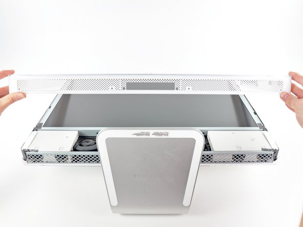
Per sollevare la mascherina anteriore dall'iMac, eseguire queste operazioni contemporaneamente:
-
Premere con i pollici le alette della memoria RAM e tenere l'iMac verso il basso.
-
Tirare con gli indici il piccolo ponte sulla mascherina anteriore verso di sé.
-
Tirare la mascherina anteriore verso l'alto con gli indici.
-
Dopo che il piccolo ponte ha liberato le alette della memoria RAM, sollevare la mascherina anteriore dal bordo inferiore, quanto basta a liberare il bordo inferiore del case posteriore.
-
-
-
Sollevare le due linguette della schermatura EMI evidenziate dal telaio dell'LCD.
-
-
Questo passaggio è privo di traduzione. Aiuta a tradurlo
-
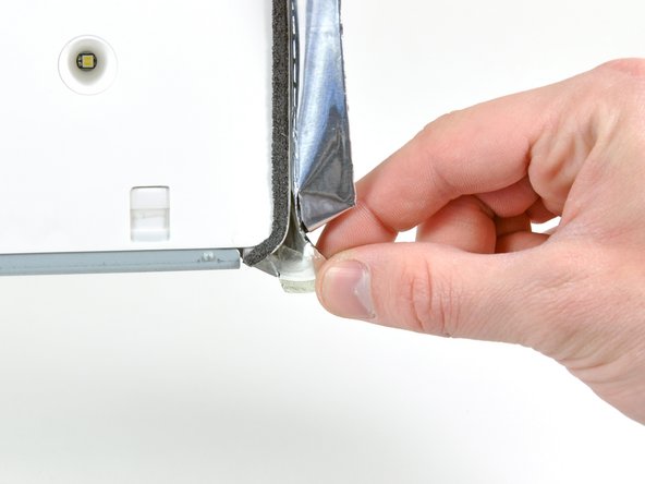
Peel back the piece of EMI tape connecting the bottom edge of the right speaker to the metal frame of the iMac.
-
Peel the tape away from the lower corner of the right speaker.
-
-
-
Questo passaggio è privo di traduzione. Aiuta a tradurlo
-
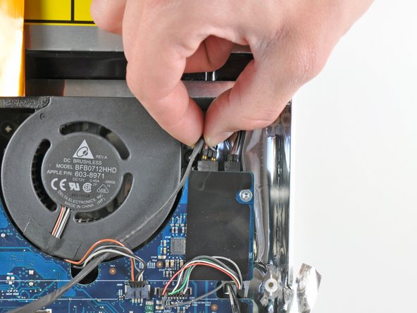
De-route the right-hand speaker's cable from between the logic board and the optical drive fan.
-
Disconnect the cable from the logic board.
-
-
Questo passaggio è privo di traduzione. Aiuta a tradurlo
-
Remove the 26 mm T10 Torx screw securing the right speaker to the iMac.
-
-
Questo passaggio è privo di traduzione. Aiuta a tradurlo
-
Pull the right speaker away from the logic board and remove it from the iMac.
-
-
Questo passaggio è privo di traduzione. Aiuta a tradurlo
-
Use the flat end of a spudger to pry both antenna connectors off their sockets on the AirPort card.
-
-
Questo passaggio è privo di traduzione. Aiuta a tradurlo
-
Use both fingertips to disconnect the camera and microphone cable from its socket on the logic board.
-
-
Questo passaggio è privo di traduzione. Aiuta a tradurlo
-
Pull the optical drive fan connector toward the top edge of the iMac to disconnect it from the logic board.
-
-
Questo passaggio è privo di traduzione. Aiuta a tradurlo
-
Pull the left speaker connector toward the top edge of the iMac to disconnect it from the logic board.
-
-
Questo passaggio è privo di traduzione. Aiuta a tradurlo
-
Pull the optical drive thermal sensor connector toward the right side of the iMac to disconnect it from its socket.
-
-
Questo passaggio è privo di traduzione. Aiuta a tradurlo
-
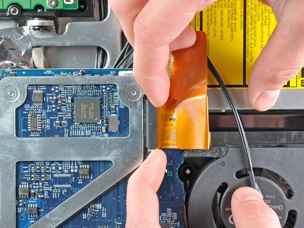
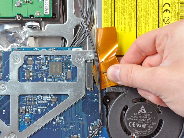
Gently pull the cable retainer on the optical drive cable ZIF socket toward the right side of the iMac.
-
Pull the optical drive ribbon cable out of its socket, being careful not to rip it in the process.
-
-
Questo passaggio è privo di traduzione. Aiuta a tradurlo
-
Disconnect the hard drive thermal sensor and hard drive fan cables from the logic board by pulling their connectors toward the top edge of the iMac.
-
-
Questo passaggio è privo di traduzione. Aiuta a tradurlo
-
Pull the CPU fan connector toward the left edge of the iMac to disconnect it from the logic board.
-
-
Questo passaggio è privo di traduzione. Aiuta a tradurlo
-
Disconnect the power button cable from the logic board.
-
-
Questo passaggio è privo di traduzione. Aiuta a tradurlo
-
Use the flat end of a spudger to pry the single Bluetooth antenna off its socket on the Bluetooth board.
-
-
Questo passaggio è privo di traduzione. Aiuta a tradurlo
-
Pull the ambient temperature sensor cable perpendicular to the face of the logic board to disconnect it from its socket.
-
-
Questo passaggio è privo di traduzione. Aiuta a tradurlo
-
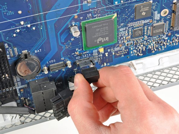
Disconnect the DC-In cable from the logic board by pulling its cable toward the right side of the iMac while depressing its locking mechanism.
-
-
Questo passaggio è privo di traduzione. Aiuta a tradurlo
-
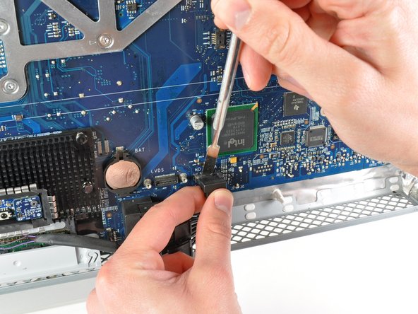
Pull the hard drive SATA data cable perpendicular to the face of the logic board to disconnect it from its socket.
-
-
Questo passaggio è privo di traduzione. Aiuta a tradurlo
-
Peel the foam tape off the top edge of the heat sink framework.
-
-
Questo passaggio è privo di traduzione. Aiuta a tradurlo
-
Remove the following ten screws:
-
Three 6.6 mm T10 Torx fine thread screws
-
Three 7 mm T10 Torx coarse thread screws
-
Two 9.3 mm T10 Torx coarse thread screws
-
Two 5.3 mm T10 Torx coarse thread screws
-
-
Questo passaggio è privo di traduzione. Aiuta a tradurlo
-
Pull the right edge of the logic board slightly away from the rear case to dislodge the rear I/O ports from their bezel.
-
Tilt the top edge of the board away from the rear case and lift the logic board assembly out of the rear case, minding any cables that may get caught.
-
-
Questo passaggio è privo di traduzione. Aiuta a tradurlo
-
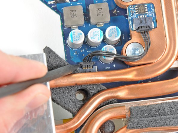
Use the tip of a spudger to push the CPU thermal sensor cable connector out of its socket on the logic board.
-
-
Questo passaggio è privo di traduzione. Aiuta a tradurlo
-
Flip the logic board over so it is heat sink side down.
-
Remove the following T10 Torx screws.
-
One short screw near the end of the heat sink.
-
Four screws around the CPU itself.
-
-
Questo passaggio è privo di traduzione. Aiuta a tradurlo
-
Remove the CPU heat sink from the logic board.
-
-
Questo passaggio è privo di traduzione. Aiuta a tradurlo
-
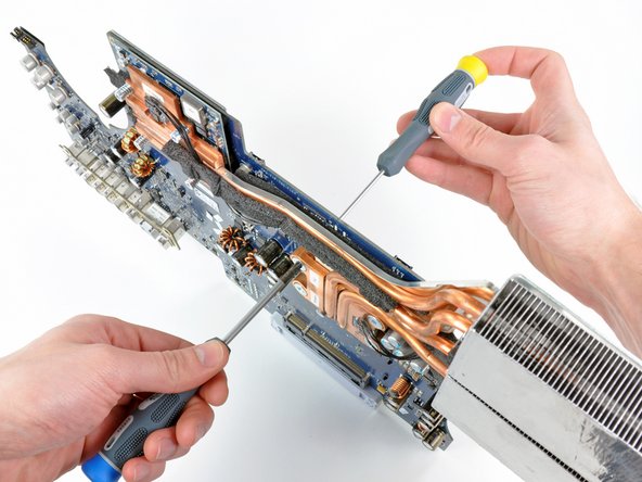
Use a small flathead screwdriver to rotate the CPU lock 180 degrees counter-clockwise.
-
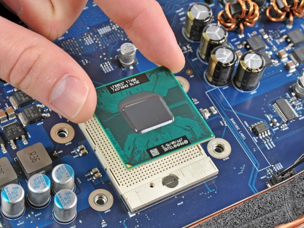
Lift the CPU straight up from its socket.
-


Annulla: non ho completato questa guida.
Altre 6 persone hanno completato questa guida.

Un commento
Just finished this refurb…. fantastic site and great guide.
The GPU was overheating, and initially, I used SMFan to increase minimum fan speeds and disabled the GPU by following this video
https://www.youtube.com/watch?v=1GDSolVl...
but obviously this limited performance, so I thought , maybe refreshing the thermal paste was help and it has - I decided to do the CPU and the GPU at the same time and the only issue was the antenna terminals broke on the Bluetooth board as I remove the cable - being a bit heavy handed.
A Bluetooth dongle later and this is all fine, the system still runs a little hot, but that’s to be expected and for a 13 year old Mac, its pretty good.
Thanks Folks - really wonderful.