Salta al contenuto principale

Questa versione può contenere modifiche errate. Passa all'ultima istantanea verificata.

Cosa ti serve

  1. Questo passaggio è privo di traduzione. Aiuta a tradurlo

    : passo 1, immagine 1 di 1
    • Lay the iMac display-side down on a flat surface.

    • Loosen the three Phillips screws securing the rear panel to the iMac.

    • These screws are captive in the iMac. The center screw will stop turning after about 3.5 turns and the outer screws will stop turning after about 5.5 turns. Do not try to remove these screws from your iMac.

  2. Questo passaggio è privo di traduzione. Aiuta a tradurlo

    : passo 2, immagine 1 di 3 : passo 2, immagine 2 di 3 : passo 2, immagine 3 di 3
    • Lift the rear panel slightly from the bottom edge of the iMac.

    • Pull the rear panel toward yourself and remove it from the iMac.

  3. Questo passaggio è privo di traduzione. Aiuta a tradurlo

    : passo 3, immagine 1 di 2 : passo 3, immagine 2 di 2
    • Rotate the center Phillips screw on the bottom of the iMac clockwise until the rear panel clamp contacts the edge of the case.

    • On our specific machine, the threaded portion of the clamp broke off the clamp body causing the center screw to turn without moving the bracket. If your machine is broken like ours, skip to the next step.

  4. Questo passaggio è privo di traduzione. Aiuta a tradurlo

    : passo 4, immagine 1 di 3 : passo 4, immagine 2 di 3 : passo 4, immagine 3 di 3
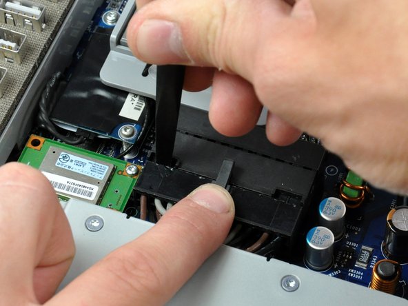
    • While depressing the connector lock, insert the flat end of a heavy duty spudger into the gap between the power supply connector and its socket.

    • Twist the heavy duty spudger to slightly separate the connector from its socket.

    • It will be necessary to work from alternate sides until the connector is free.

    • Your power supply may have an ambient light sensor cable attached from the power supply to the logic board. If so, carefully use a spudger to push out the cable towards you using the sides of the cable alternatively to help you slide it out.

  5. Questo passaggio è privo di traduzione. Aiuta a tradurlo

    : passo 5, immagine 1 di 1
    • Pull the power supply connector straight away from its socket on the logic board.

    • This step is very simple if you remove the power supply first.

  6. Questo passaggio è privo di traduzione. Aiuta a tradurlo

    : passo 6, immagine 1 di 1
    • Remove the three Phillips screws securing the power supply to the chassis.

    • All three screws are captive in the power supply.

    • To aid in removal, it may be helpful to lift the center screw slightly away from the midplane.

  7. Questo passaggio è privo di traduzione. Aiuta a tradurlo

    : passo 7, immagine 1 di 2 : passo 7, immagine 2 di 2
    • There are several capacitors mounted to the logic board in close proximity to the power supply. Try not to disturb them, as they are delicate and may break off the board.

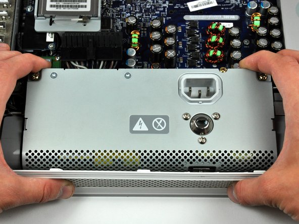
    • Grab the power supply from each side and rotate its top edge toward yourself until it clears the logic board.

    • Lift the power supply out of the midplane.

    • The power supply requires a large amount of force to remove. You may need to slightly bend the edge of the front case toward yourself for enough clearance to remove the power supply.

Linea Traguardo

Altre 35 persone hanno completato questa guida.

Un commento

very clear instructions... will replace my ps and then repair the faulty one.

do you have an idea what components usually fail or is it a mix of things?

Thanks

r@boarman.net

Irene1545 - Replica

Aggiungi Commento

Visualizza Statistiche:

Ultime 24 Ore: 0

Ultimi 7 Giorni: 7

Ultimi 30 Giorni: 11

Tutti i Tempi: 33,719