Questa versione può contenere modifiche errate. Passa all'ultima istantanea verificata.
Cosa ti serve
-
-
Usa una moneta per ruotare la vite di bloccaggio della batteria di 90 gradi in senso orario.
-
Solleva la batteria fuori dal computer.
-
-
Questo passaggio è privo di traduzione. Aiuta a tradurlo
-
Pull the keyboard release tabs (shown in yellow) toward you and lift up on the keyboard until it pops free.
-
If the keyboard does not come free, use a small flathead screwdriver to turn the keyboard locking screw (shown in orange) 180 degrees in either direction and try again.
-
Flip the keyboard over, away from the screen, and rest it face-down on the trackpad area.
-
-
Questo passaggio è privo di traduzione. Aiuta a tradurlo
-
Loosen the four silver Phillips screws that secure the RAM shield.
-
-
Questo passaggio è privo di traduzione. Aiuta a tradurlo
-
Pull the keyboard cable up from the logic board, holding the cable as close to the connector as possible.
-
-
-
Chiudi il display e capovolgi il computer.
-
Rimuovi le tre viti esagonali usando un cacciavite Torx T8.
-
-
Questo passaggio è privo di traduzione. Aiuta a tradurlo
-
There is a slot on the wall of the battery compartment that locks the lower case in place. Use a small flathead screwdriver to pry out the slot's lower rim and pull up on the lower case to free the slot from the tabs holding it.
-
-
Questo passaggio è privo di traduzione. Aiuta a tradurlo
-
Run a spudger along the seam between the lower case and upper case on the front of the computer to free the tabs locking the lower case. Pull up on the lower case and continue to use the spudger as necessary until you hear three distinct clicks.
-
-
Questo passaggio è privo di traduzione. Aiuta a tradurlo
-
Continue to run the spudger around the front, right corner. There are two tabs on the port side of the computer, one near the front corner and one near the sound-out port.
-
-
Questo passaggio è privo di traduzione. Aiuta a tradurlo
-
There are three tabs over the optical drive that must be released before the lower case can come off. Slide the spudger into the lower case above the optical drive and run it toward the back of the computer until you hear three distinct clicks.
-
-
Questo passaggio è privo di traduzione. Aiuta a tradurlo
-
Turn the computer so that the back is facing you and pull the lower case up and toward you until the back tabs pop free.
-
-
Questo passaggio è privo di traduzione. Aiuta a tradurlo
-
Remove the small greasy springs with white plastic caps from either side of the battery contacts.
-
-
-
Questo passaggio è privo di traduzione. Aiuta a tradurlo
-
Remove the following 10 screws from the bottom shield:
-
Six 3 mm Phillips
-
Three 7.5 mm Phillips
-
One 14 mm Phillips
-
-
Questo passaggio è privo di traduzione. Aiuta a tradurlo
-
Remove the single Phillips screw securing the DC-In board.
-
-
Questo passaggio è privo di traduzione. Aiuta a tradurlo
-
Angle the DC-In board out of its compartment.
-
-
Questo passaggio è privo di traduzione. Aiuta a tradurlo
-
Lift the DC-In cable from the adhesive attaching it to the logic board.
-
-
Questo passaggio è privo di traduzione. Aiuta a tradurlo
-
Disconnect the DC-In cable from the logic board.
-
-
Questo passaggio è privo di traduzione. Aiuta a tradurlo
-
Remove the following 11 screws from the bottom of the computer:
-
Three 3 mm Phillips around the battery compartment.
-
Three 4.5 mm Phillips along the optical drive bezel. (a magnetic screwdriver may help to lift these screws out)
-
One 12 mm Phillips in the lower right corner.
-
Four 14.5 mm Phillips.
-
-
Questo passaggio è privo di traduzione. Aiuta a tradurlo
-
Turn over the computer and open it.
-
Remove the 3 Phillips screws from the edges of the keyboard area.
-
-
Questo passaggio è privo di traduzione. Aiuta a tradurlo
-
Lift the upper case and use a spudger or your finger to disconnect the trackpad connector hidden beneath the white plastic tab.
-
-
Questo passaggio è privo di traduzione. Aiuta a tradurlo
-
Lift the upper case enough to disconnect the blue and white power cable from the logic board. Using your fingernails, carefully pry the connector from its socket.
-
Carefully disconnect the multicolored speaker cable from the logic board in the same fashion.
-
-
Questo passaggio è privo di traduzione. Aiuta a tradurlo
-
Remove the following 16 screws:
-
Thirteen 3 mm Phillips.
-
One 3 mm Phillips.
-
Two 4 mm Phillips.
-
-
Questo passaggio è privo di traduzione. Aiuta a tradurlo
-
Lift the top shield up from the right side, minding the upper left corner which may catch on the metal framework.
-
-
Questo passaggio è privo di traduzione. Aiuta a tradurlo
-
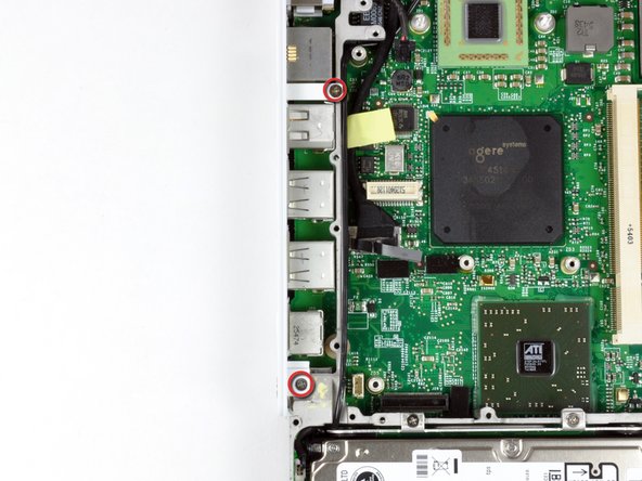
Remove the two Phillips screws at the corners of the modem.
-
Remove the two Phillips screws at the corners of the modem.
-
-
Questo passaggio è privo di traduzione. Aiuta a tradurlo
-
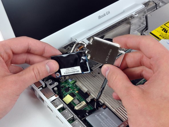
Use a spudger to pry the modem up from the end nearest the AirPort card to separate its connector from a socket on the logic board.
-
Use your hands to seperate the modem from the modem shield.
-
-
Questo passaggio è privo di traduzione. Aiuta a tradurlo
-
Disconnect the RJ-11 cable from the end of the modem.
-
-
Questo passaggio è privo di traduzione. Aiuta a tradurlo
-
Remove the three 3 mm Phillips screws securing the AirPort card bracket to the metal framework.
-
Lift the AirPort card retaining bracket up and out of the computer.
-
-
Questo passaggio è privo di traduzione. Aiuta a tradurlo
-
Remove the two 3 mm Phillips screws securing the AirPort card to the logic board.
-
-
Questo passaggio è privo di traduzione. Aiuta a tradurlo
-
Using a spudger, pry up on the AirPort card from the end nearest the hard drive to separate the connector from its socket on the logic board.
-
-
Questo passaggio è privo di traduzione. Aiuta a tradurlo
-
De-route the AirPort antenna cables from above the heat sink and lay them aside.
-
-
Questo passaggio è privo di traduzione. Aiuta a tradurlo
-
Remove the following 9 screws and 2 nuts from the heat sink:
-
Four 3 mm Phillips from around the fan and the heat sink bracket. The bracket can also be removed at this point.
-
One 11.5 mm (left) and one 4.5 mm (right) Phillips from the plastic fingers of the hinge grill.
-
One 4.5 mm Phillips at the top right corner of the heat sink.
-
Two 6 mm Phillips on the lower left corner and face of the heat sink.
-
Two 4 mm screw nuts with attached springs from either side of the heat sink.
-
-
Questo passaggio è privo di traduzione. Aiuta a tradurlo
-
If necessary, use a spudger to pry up the heat sink from the left side near the hard drive.
-
While lifting straight up on the hinge grill with your right hand, lift the heat sink with your left hand from the end nearest the hard drive and remove the heat sink assembly from the computer.
-
-
Questo passaggio è privo di traduzione. Aiuta a tradurlo
-
Remove the two Phillips screws securing the white plastic fingers of the I/O bezel to the metal framework.
-
-
Questo passaggio è privo di traduzione. Aiuta a tradurlo
-
Lift up the left side of the computer and slide the I/O bezel away.
-
-
Questo passaggio è privo di traduzione. Aiuta a tradurlo
-
Wedge a spudger between the RJ-11 board and the metal framework and slide the board to the left, off of the logic board.
-
-
Questo passaggio è privo di traduzione. Aiuta a tradurlo
-
Use the black plastic loop to disconnect the display data cable from the logic board.
-
-
Questo passaggio è privo di traduzione. Aiuta a tradurlo
-
Remove the four 4mm Phillips screws securing the hard drive to the metal framework.
-
Carefully lift up the hard drive.
-
-
Questo passaggio è privo di traduzione. Aiuta a tradurlo
-
Disconnect the microphone cable at the front of the computer, between the left side of the hard drive enclosure and the metal framework.
-
-
Questo passaggio è privo di traduzione. Aiuta a tradurlo
-
Disconnect the Reed Switch board connector from the logic board.
-
-
Questo passaggio è privo di traduzione. Aiuta a tradurlo
-
1) With your fingernails, grasp the locking bar on either side and pull up a small amount (about 1/16" or 2 mm).
-
2) After disengaging the locking bar, slide the cable out of the connector.
-
-
Questo passaggio è privo di traduzione. Aiuta a tradurlo
-
Release the optical drive ribbon clamp as described above. Slide the optical drive ribbon out of its connector.
-
-
Questo passaggio è privo di traduzione. Aiuta a tradurlo
-
Close the display and flip the computer over.
-
Remove the two 5mm Phillips screws securing the battery connector to the metal framework.
-
Lift the battery connector out of the metal framework and disconnect it from the logic board.
-
-
Questo passaggio è privo di traduzione. Aiuta a tradurlo
-
Remove the following 8 screws:
-
Eight 3.5 mm Phillips.
-
Two 3.5 mm Phillips near the sleep light connector.
-
One 3.5 mm Phillips with a large head in the lower left corner.
-
One 4.5 mm Phillips.
-
From top to bottom, disconnect the inverter, fan, and sleep light cables from the logic board.
-
-
Questo passaggio è privo di traduzione. Aiuta a tradurlo
-
Lift the logic board up from the right side, and slide it up and out of the computer.
-


Annulla: non ho completato questa guida.
Altre 20 persone hanno completato questa guida.
