Questa guida ha delle modifiche più recenti. Passa all'ultima versione non verificata.
Introduzione
Change out the entire display assembly, including the inverter, Airport antenna, hinges and plastic casing.
Cosa ti serve
-
-
Lay your iBook upside down on a flat surface.
-
Use a coin to rotate the battery locking screw 90 degrees clockwise.
-
Lift the battery out of the computer.
-
-
-
Pull the keyboard release tabs toward you and lift up on the keyboard until it pops free.
-
Flip the keyboard over, away from the screen, and rest it face-down on the trackpad area.
-
-
-
Use a spudger or small flathead screwdriver to remove the three rubber feet from the lower case.
-
-
-
-
Remove the following 4 screws from the bottom shield:
-
Two 3 mm Phillips.
-
Two 7.5 mm Phillips.
-
-
-
Remove the two Phillips screws securing the DC-In board, removing tape as necessary.
-
-
-
Remove the two 3 mm Phillips screws inside the left edge of the battery tray.
-
Three 3 mm Phillips around the battery compartment.
-
Three 4.5 mm Phillips along the optical drive bezel. (a magnetic screwdriver may help to lift these screws out)
-
One 12 mm Phillips in the lower right corner.
-
Four 14.5 mm Phillips.
-
-
-
Remove the following 7 screws from the edges of the keyboard area.
-
Three 2 mm Phillips along the right edge.
-
One 4.5 mm Phillips underneath where the magnet was.
-
One 6 mm Phillips with a small head in the lower left corner.
-
Two 6 mm Phillips with large heads, one in the upper left corner and one in the middle.
-
-
-
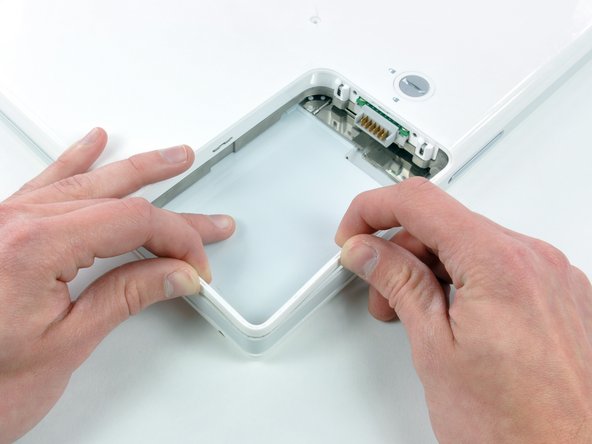
Carefully lift the upper case slightly and move it toward the front of the computer to reveal the trackpad connector. Use a spudger or your finger to disconnect the trackpad connector hidden beneath the white plastic tab.
-
After disconnecting the track pad connector, carefully rotate the upper case away from you and rest it against the display.
-
-
-
Remove the fifteen 3 mm Phillips screws securing the top shield to the computer.
-
Remove the following 16 screws:
-
Thirteen 3 mm Phillips.
-
One 3 mm Phillips. (actual screw not present in image)
-
Two 4 mm Phillips.
-
-
-
Remove the following 4 screws:
-
One 3 mm Phillips in the channel between the optical drive and fan.
-
Two 6 mm Phillips from the upper and bottom end of the drive bezel.
-
One 6 mm Phillips with a collar from bracket extending from the lower left corner of the drive.
-
-
-
Remove the following three screws:
-
Two 3mm Phillips screws.
-
One 7.5 mm Phillips screw.
-
Lift the small plastic retaining bracket up and out of the computer.
-
-
-
Turn the computer back over.
-
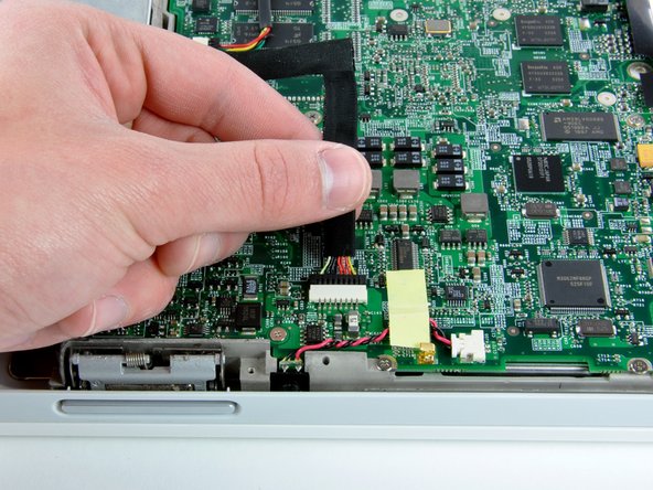
Disconnect the microphone cable at the front of the computer, between the left side of the hard drive and the metal framework, removing tape as necessary.
-
Although not absolutely essential, removal of the hard drive will give enough space to remove the connector with your fingers.
-


To reassemble your device, follow these instructions in reverse order.
To reassemble your device, follow these instructions in reverse order.
Annulla: non ho completato questa guida.
Altre 17 persone hanno completato questa guida.
