Salta al contenuto principale

Questa versione può contenere modifiche errate. Passa all'ultima istantanea verificata.

Cosa ti serve

  1. , Batteria: passo 1, immagine 1 di 1
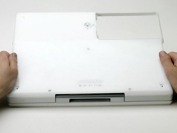
    • Utilizza una moneta per ruotare la vite che blocca la batteria di 90 gradi in senso orario.

    • Estrai la batteria dal computer.

  2. , Tastiera: passo 2, immagine 1 di 1
    • Tira le alette di rilascio della tastiera (evidenziate in rosso) verso di te e solleva la tastiera finché non viene fuori.

    • Se la tastiera non viene fuori, utilizza un piccolo cacciavite a taglio per ruotare la vite che blocca la tastiera di 180 gradi in qualsiasi direzione e riprova.

    • Capovolgi la tastiera, lontana dallo schermo, e posizionala a testa in giù sull'area del trackpad.

  3. : passo 3, immagine 1 di 1
    • Se il tuo computer non ha una scheda Airport installata, salta il passo di rimozione della copertura della RAM.

    • Spingi la chiusura a filo verso la scheda Airport e tirala su per liberarla dalla copertura della RAM.

  4. : passo 4, immagine 1 di 1
    • Afferra l'aletta di plastica trasparente sulla scheda Airport e tira verso destra.

  5. : passo 5, immagine 1 di 1
    • Tieni la scheda Airport in una mano e utilizza l'altra mano per rimuovere il cavo dell'antenna.

  6. : passo 6, immagine 1 di 1
    • Rimuovi le due viti a croce Phillips che fissano la copertura della RAM.

  7. : passo 7, immagine 1 di 1
    • Afferra la staffa metallica sopra alla copertura della RAM e tira verso l'alto per rimuovere la copertura.

  8. : passo 8, immagine 1 di 1
    • Tira su il cavo della tastiera dalla scheda logica, tenendo il cavo il più vicino possibile al connettore.

  9. , Case inferiore: passo 9, immagine 1 di 1
    • Utilizza uno spillo per rimuovere i tre piedini in gomma dal case inferiore.

  10. : passo 10, immagine 1 di 1
    • Rimuovi le tre viti a croce Phillips appena scoperte.

  11. : passo 11, immagine 1 di 1
    • Utilizza uno spudger o un piccolo cacciavite a taglio per fare leva e sollevare i tre anelli metallici che ospitavano i piedini di gomma.

  12. : passo 12, immagine 1 di 1
    • Rimuovi le tre viti esagonali utilizzando un cacciavite Torx T8.

    • La vite al centro è più corta rispetto alle altre due.

  13. : passo 13, immagine 1 di 1
    • Rimuovi le due viti a croce Phillips su entrambi i lati dei contatti della batteria.

  14. : passo 14, immagine 1 di 1
    • Respira profondamente. Ci aspettano tempi difficili, ma promettiamo che il case inferiore si staccherà.

    • Spingi i piccoli cerchi del case inferiore che circondano lo scompartimento della batteria dentro, piegandoli oltre le alette, e poi solleva verso l'alto per liberare quell'angolo del case inferiore.

  15. : passo 15, immagine 1 di 1
    • C'è uno slot sulla parete dello scompartimento della batteria che blocca in posizione il case inferiore.

    • Utilizza un piccolo cacciavite a taglio per fare leva e tirare fuori il cerchio dello slot inferiore e tirare su sul case inferiore per liberare lo slot dalle alette che lo tengono.

  16. : passo 16, immagine 1 di 1
    • Passa uno spudger lungo la linea di giunzione tra il case inferiore e il case superiore sulla parte anteriore del computer per liberare le alette che bloccano il case inferiore.

    • Tira su sul case inferiore e continua a utilizzare uno spudger finché necessario fino a sentire tre click distinti.

  17. : passo 17, immagine 1 di 1
    • Continua a passare lo spudger intorno all'angolo anteriore destro.

    • Ci sono due alette su lato delle porte del computer, una vicino all'angolo anteriore e una vicino alla porta della riproduzione del suono.

  18. : passo 18, immagine 1 di 1
    • Una volta che la parte anteriore e i lati del case inferiore sono liberi, capovolgi il computer di modo che la parte posteriore sia rivolta verso di te.

    • Spingi su il case inferiore e portalo verso di te finché le alette posteriori non saltano fuori.

    • Potrebbe essere utile scuotere il case su e giù.

  19. : passo 19, immagine 1 di 1
    • Rimuovi le piccole molle unte con dei tappi bianchi in plastica da entrambi i lati dei contatti della batteria.

  20. Questo passaggio è privo di traduzione. Aiuta a tradurlo

    : passo 20, immagine 1 di 1
    • All of the screws in the following step have small heads - the screws with larger heads hold the bottom shield on.

    • Remove the following 9 screws on the bottom of the computer:

    • Three 3 mm Phillips around the battery compartment.

    • Three 5 mm Phillips on the left and bottom edges.

    • Three 14.5 mm Phillips on the top and right edges (you may have to peel back the foil tape to reveal the screw near the security lock slot).

  21. Questo passaggio è privo di traduzione. Aiuta a tradurlo

    : passo 21, immagine 1 di 1
    • Turn over the computer and open it.

    • Pry up the magnet covering a Phillips screw near the middle of the computer.

    • You may need to peel back the serial number sticker to access the magnet.

  22. Questo passaggio è privo di traduzione. Aiuta a tradurlo

    : passo 22, immagine 1 di 1
    • Remove the following 3 screws on the edges of the keyboard area:

    • Two 6 mm Phillips underneath the keyboard area.

    • One 9 mm Phillips above the keyboard area.

    • On some models, there may also be a screw under the magnet you just removed. If so, remove the screw at this point.

  23. Questo passaggio è privo di traduzione. Aiuta a tradurlo

    : passo 23, immagine 1 di 1
    • This is a diagram of the ribbon clamp connectors you will disconnect in the next step.

    • With your fingernails, grasp the locking bar on either side and pull up a small amount (about 1/16" or 2 mm).

    • After disengaging the locking bar, slide the cable out of the connector.

  24. Questo passaggio è privo di traduzione. Aiuta a tradurlo

    : passo 24, immagine 1 di 1
    • Loosen the trackpad connector by pulling the top piece up slightly, freeing the trackpad ribbon.

    • Slide the orange trackpad ribbon out of the connector.

  25. Questo passaggio è privo di traduzione. Aiuta a tradurlo

    : passo 25, immagine 1 di 1
    • Use a straightened paperclip to open the optical drive tray, and pull it out about halfway.

  26. Questo passaggio è privo di traduzione. Aiuta a tradurlo

    : passo 26, immagine 1 di 1
    • Don't lift the upper case off the computer yet as there are still two cables left to disconnect.

    • Lift the upper case from the left side and use your other hand to pull out the right side in order to clear the power receptacle.

  27. Questo passaggio è privo di traduzione. Aiuta a tradurlo

    : passo 27, immagine 1 di 1
    • The connectors at the ends of the cables are attached very firmly to the sockets on the logic board. Pulling directly on the cable will either separate the cable from its connector or the socket from the logic board.

    • Lift the upper case enough to disconnect the blue and white power cable from the logic board.

    • Using your fingernails or a dental pick, carefully pry the connector from its socket.

    • Make sure you are pulling only on the connector and not on the socket.

  28. Questo passaggio è privo di traduzione. Aiuta a tradurlo

    : passo 28, immagine 1 di 1
    • Lift the upper case off completely and disconnect the red and black speaker cable from the logic board.

    • Make sure you are pulling only on the connector and not on the socket.

  29. Questo passaggio è privo di traduzione. Aiuta a tradurlo

    : passo 29, immagine 1 di 1
    • Remove the following 16 screws:

    • Five 3 mm Phillips (these have smaller heads than the others).

    • Three 5 mm Phillips.

    • Eight 6 mm Phillips.

  30. Questo passaggio è privo di traduzione. Aiuta a tradurlo

    • If you have already removed the yellow tape, skip this step.

    • Peel back three strips of yellow tape in the bottom, left corner.

    • Peel back one strip of foil tape near the audio-out port, one near where the trackpad connects to the logic board, and one near where the screen latch used to be.

  31. Questo passaggio è privo di traduzione. Aiuta a tradurlo

    : passo 31, immagine 1 di 1
    • Lift the top shield up from the right side, minding the upper left corner, which may catch on the metal framework.

  32. Questo passaggio è privo di traduzione. Aiuta a tradurlo

    : passo 32, immagine 1 di 1
    • Remove the single Phillips screw to the right of the hard drive connector.

  33. Questo passaggio è privo di traduzione. Aiuta a tradurlo

    : passo 33, immagine 1 di 1
    • At the front edge of the hard drive, lift up on the transparent orange tape to disconnect the ribbon cable from the main board.

  34. Questo passaggio è privo di traduzione. Aiuta a tradurlo

    : passo 34, immagine 1 di 1
    • Peel back the black tape to free the microphone cable from the hard drive.

  35. Questo passaggio è privo di traduzione. Aiuta a tradurlo

    : passo 35, immagine 1 di 1
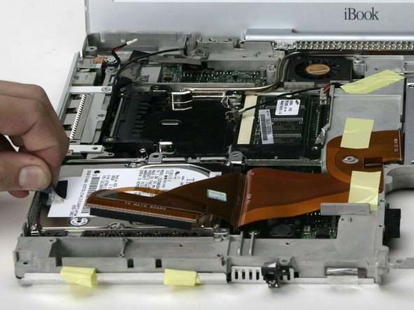
    • Lift the hard drive out of the computer and turn the hard drive over. Use the transparent orange loop to disconnect the hard drive ribbon cable from the hard drive.

    • This is a bit tricky. Try rocking the cable gently from side to side while applying even pressure. If you bend the pins, do your best to straighten them, using the hard drive cable as a guide.

  36. Questo passaggio è privo di traduzione. Aiuta a tradurlo

    : passo 36, immagine 1 di 1
    • Remove the metal brackets from either side of the hard drive (if they're still there).

    • With the pins facing away from you, and the label facing up, the bracket with a tab in the middle and a metal slot on it goes on the left side of the drive; the other bracket, of course, goes on the right.

  37. Questo passaggio è privo di traduzione. Aiuta a tradurlo

    : passo 37, immagine 1 di 1
    • Remove two T8 Torx screws from either side of the hard drive (four screws total).

Linea Traguardo

Altre 36 persone hanno completato questa guida.

Documenti Allegati

iRobot

Membro da: 09/24/09

1 Reputazione

636 Guide realizzate

3 Commenti

I don't think you have to remove the bottom case to replace the hard drive, at least on the iBook 800MHz 32MB VRAM.

Captain Phingerspex - Replica

Just replaced the original 20GB HDD with a 40GB in an iBook G3/600 (mid 2002); removal of the case bottom IS necessary on this model. It was more "tedious" than "difficult" (37 steps in, 37 steps out), although I had previous experience on this same machine upgrading RAM to 640MB and installing an AirPort card.

UNSC Jon 117 - Replica

step 21 is not necessary and if you care about the mac having it’s original sticker I would not advise doing what it says… The “magnet” is not removable and if the system is original the sticker will not peal up easily.

Michael Napodano - Replica

Aggiungi Commento

Visualizza Statistiche:

Ultime 24 Ore: 3

Ultimi 7 Giorni: 7

Ultimi 30 Giorni: 39

Tutti i Tempi: 35,799