Questa versione può contenere modifiche errate. Passa all'ultima istantanea verificata.
Cosa ti serve
-
-
Usa una moneta per ruotare la vite di bloccaggio della batteria di 90° in senso orario.
-
Solleva la batteria dal portatile.
-
-
Questo passaggio è privo di traduzione. Aiuta a tradurlo
-
Pull the keyboard release tabs toward you and lift up on the keyboard until it pops free.
-
If the keyboard does not come free, use a small flathead screwdriver to turn the keyboard locking screw 180 degrees in either direction and try again.
-
Flip the keyboard over, away from the screen, and rest it face-down on the trackpad area.
-
-
Questo passaggio è privo di traduzione. Aiuta a tradurlo
-
Push the wire clasp toward the Airport card and pull it up to free it from the RAM shield.
-
-
Questo passaggio è privo di traduzione. Aiuta a tradurlo
-
Grasp the clear plastic tab on the Airport card and pull toward the right.
-
-
Questo passaggio è privo di traduzione. Aiuta a tradurlo
-
Hold the Airport card in one hand and use your other hand to remove the antenna cable.
-
-
Questo passaggio è privo di traduzione. Aiuta a tradurlo
-
Remove the two 2.5 mm Phillips screws that secure the RAM shield.
-
-
Questo passaggio è privo di traduzione. Aiuta a tradurlo
-
Grasp the metal bracket on top of the RAM shield and pull upward to remove the shield.
-
-
Questo passaggio è privo di traduzione. Aiuta a tradurlo
-
Pull the keyboard cable up from the logic board, holding the cable as close to the connector as possible.
-
-
-
-
Respira profondamente. Potresti dover provare diverse volte, ma ti promettiamo che il case inferiore viene fuori.
-
Spingi dentro i bordi sottili del case inferiore che circonda il vano batterie, piegando in dentro le alette, dopodiché sollevalo per liberare quell’angolo del case inferiore.
-
-
-
Una volta che la parte anteriore e i lati del case inferiore sono liberi, gira il computer in modo che la parte posteriore sia rivolta verso di te e tira il case inferiore in alto e verso di te fino a quando le alette non si liberano (potrebbe esserti utile muovere il case su e giù).
-
-
Questo passaggio è privo di traduzione. Aiuta a tradurlo
-
Remove the following 4 screws on the bottom of the computer:
-
Two 3 mm Phillips from the left side of the computer.
-
One 4.5 mm Phillips near the latch mechanism (this screw may be missing in 800 MHz iBooks)
-
One 14.2 mm Phillips near the front, right corner.
-
-
Questo passaggio è privo di traduzione. Aiuta a tradurlo
-
Use a straightened paperclip to open the optical drive tray.
-
-
Questo passaggio è privo di traduzione. Aiuta a tradurlo
-
Pull the optical drive out just enough so that you can access and remove a Phillips screw near the battery compartment.
-
-
Questo passaggio è privo di traduzione. Aiuta a tradurlo
-
Pull the optical drive a bit more so that you can access and remove a second Phillips screw near the power receptacle.
-
-
Questo passaggio è privo di traduzione. Aiuta a tradurlo
-
Turn over the computer and open it.
-
Use tweezers (or a refrigerator magnet) to remove the magnet covering a Phillips screw near the middle of the computer.
-
-
Questo passaggio è privo di traduzione. Aiuta a tradurlo
-
Remove the following 4 screws on the edges of the keyboard area.
-
One 4.5 mm Phillips underneath where the magnet was.
-
Three 6 mm Phillips in plastic depressions.
-
-
Questo passaggio è privo di traduzione. Aiuta a tradurlo
-
Peel up the foil tape covering the speaker cable near the ports.
-
-
Questo passaggio è privo di traduzione. Aiuta a tradurlo
-
1) With your fingernails, grasp the locking bar on either side and pull up a small amount (about 1/16" or 2 mm).
-
2) After disengaging the locking bar, slide the cable out of the connector.
-
-
Questo passaggio è privo di traduzione. Aiuta a tradurlo
-
Loosen the trackpad connector by pulling the top piece up slightly, freeing the trackpad ribbon.
-
Slide the orange trackpad ribbon out of the connector.
-
-
Questo passaggio è privo di traduzione. Aiuta a tradurlo
-
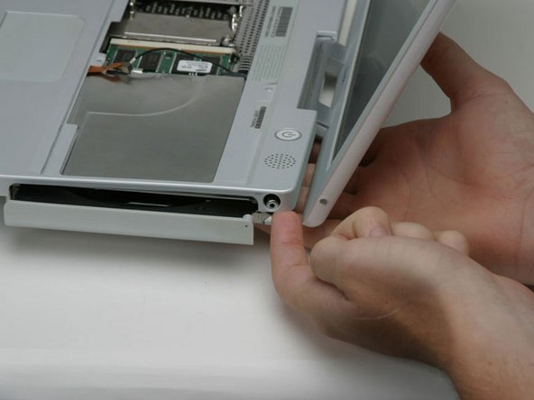
Lift the upper case from the left side and use your other hand to pull out the right side in order to clear the power receptacle.
-
-
Questo passaggio è privo di traduzione. Aiuta a tradurlo
-
Lift the upper case enough to disconnect the blue and white power cable from the logic board. Using your fingernails or a dental pick, carefully pry the connector from its socket. Make sure you're pulling only on the connector and not on the socket.
-
-
Questo passaggio è privo di traduzione. Aiuta a tradurlo
-
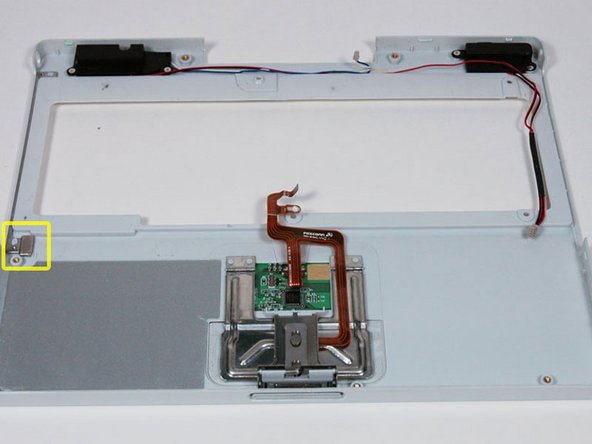
Lift the upper case off completely and disconnect the red and black speaker cable from the logic board. As before, make sure you're pulling only on the connector and not on the socket.
-


Annulla: non ho completato questa guida.
Altre 15 persone hanno completato questa guida.
