Questa versione può contenere modifiche errate. Passa all'ultima istantanea verificata.
Cosa ti serve
-
-
Premi il pulsante di rilascio della batteria sulla parte superiore del controller.
-
Rimuovi il supporto della batteria dal controller.
-
-
Questo passaggio è privo di traduzione. Aiuta a tradurlo
-
Use a pair of tweezers to peel the barcode sticker from the battery compartment.
-
-
Questo passaggio è privo di traduzione. Aiuta a tradurlo
-
Remove the seven 9.3 mm T8 Security Torx screws securing the rear case to the front case.
-
-
Questo passaggio è privo di traduzione. Aiuta a tradurlo
-
Insert a Spudger between the front and rear cases along the left edge of the controller.
-
Rotate the spudger toward the front of the controller, prying the two cases apart.
-
-
Questo passaggio è privo di traduzione. Aiuta a tradurlo
-
Insert a spudger between the front and rear cases, near the headphone jack.
-
Rotate the spudger toward the front of the controller to pry the two cases apart.
-
-
Questo passaggio è privo di traduzione. Aiuta a tradurlo
-
Grasp the controller by the battery compartment and the headphone jack.
-
Lift the battery compartment away from the headphone jack, separating the rear case from the front case and logic board.
-
-
-
Questo passaggio è privo di traduzione. Aiuta a tradurlo
-
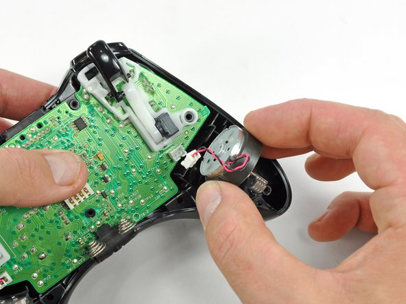
Use the flat end of a spudger to remove the vibration motor cable, moving it upward from its socket on the logic board.
-
Lift the vibration motor out of the front case.
-
-
Questo passaggio è privo di traduzione. Aiuta a tradurlo
-
Remove the vibration motor from the other side of the controller using the same method previously described.
-
-
Questo passaggio è privo di traduzione. Aiuta a tradurlo
-
Lifting from the headphone jack and power plug, remove the logic board from the front case.
-
-
Questo passaggio è privo di traduzione. Aiuta a tradurlo
-
Lift the bumper panel off of the front case.
-
-
Questo passaggio è privo di traduzione. Aiuta a tradurlo
-
Remove the rubber pad from the back of the D-pad.
-
-
Questo passaggio è privo di traduzione. Aiuta a tradurlo
-
Remove the two 7.0 mm silver Phillips screws from the back of the D-pad.
-
-
Questo passaggio è privo di traduzione. Aiuta a tradurlo
-
Use a pair of tweezers and squeeze the clips together to release the D-pad from its backing.
-
-
Questo passaggio è privo di traduzione. Aiuta a tradurlo
-
Lift the D-pad backing out of its compartment on the front case.
-
The D-pad remains below the front case.
-
-
Questo passaggio è privo di traduzione. Aiuta a tradurlo
-
Remove the rubber pad from the back of the input buttons.
-
-
Questo passaggio è privo di traduzione. Aiuta a tradurlo
-
Using a pair or tweezers, remove the following buttons from the front panel:
-
A Button
-
B Button
-
X Button
-
Y Button
-
Start Button
-
Select Button
-
Guide Button
-
-
Questo passaggio è privo di traduzione. Aiuta a tradurlo
-
Using a pair of tweezers, remove the LED ring from the front panel.
-
-
Questo passaggio è privo di traduzione. Aiuta a tradurlo
-
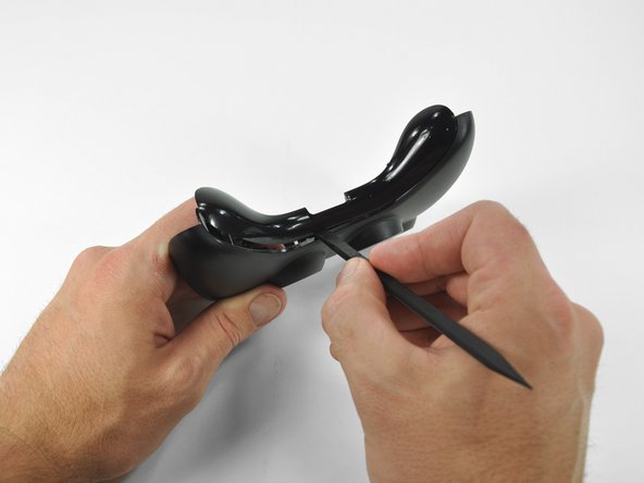
Insert a spudger between the lower panel and front case.
-
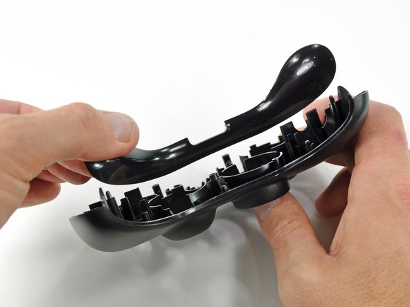
Slide the spudger along the gap between the two case components.
-
Lift the lower panel off of the front case.
-


Annulla: non ho completato questa guida.
Altre 18 persone hanno completato questa guida.

