Salta al contenuto principale

Questa versione può contenere modifiche errate. Passa all'ultima istantanea verificata.

Attrezzature medicali
Né iFixit né questa guida di riparazione sono approvati dal produttore del dispositivo medicale o affiliati ad esso.

Cosa ti serve

  1. Questo passaggio è privo di traduzione. Aiuta a tradurlo

    : passo 1, immagine 1 di 2 : passo 1, immagine 2 di 2
    • Unplug the AC power connection cable.

  2. Questo passaggio è privo di traduzione. Aiuta a tradurlo

    : passo 2, immagine 1 di 3 : passo 2, immagine 2 di 3 : passo 2, immagine 3 di 3
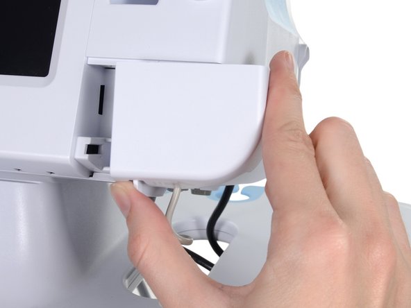
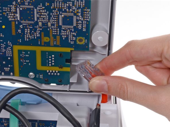
    • Place your thumb and forefinger on the blood pressure (NIBP) hose connector. Squeeze the side tabs until the connector releases.

    • Always grasp the hose by the connector. Do not pull on the hose itself.

    • Pull the connector away from the connector port.

  3. Questo passaggio è privo di traduzione. Aiuta a tradurlo

    : passo 3, immagine 1 di 3 : passo 3, immagine 2 di 3 : passo 3, immagine 3 di 3
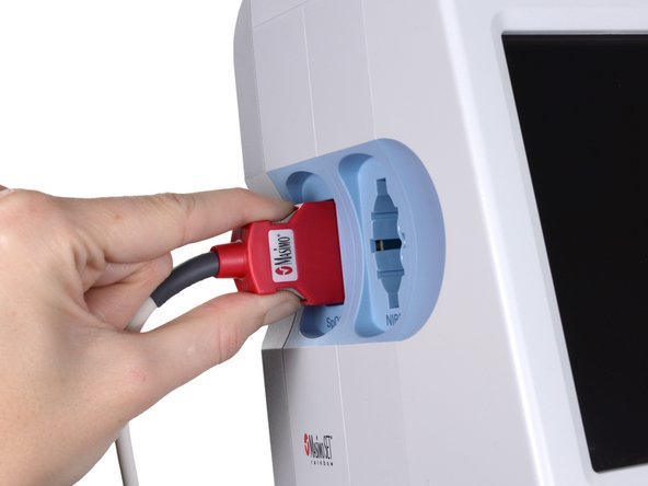
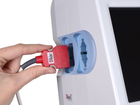
    • Place your thumb and forefinger on the Pulse oximetry (SpO2 or combined SpO2/SpHb) cable connector. Squeeze the side tabs until the connector releases.

    • Always grasp the cable by the connector. Do not pull on the cable itself.

    • Pull the connector away from the connector port.

  4. Questo passaggio è privo di traduzione. Aiuta a tradurlo

    : passo 4, immagine 1 di 2 : passo 4, immagine 2 di 2
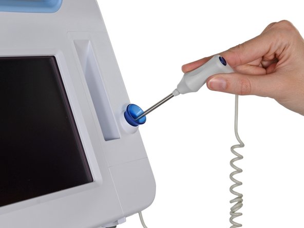
    • Grasp the temperature probe and pull it up to remove it from the monitor.

  5. Questo passaggio è privo di traduzione. Aiuta a tradurlo

    : passo 5, immagine 1 di 3 : passo 5, immagine 2 di 3 : passo 5, immagine 3 di 3
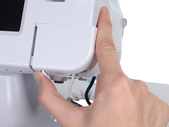
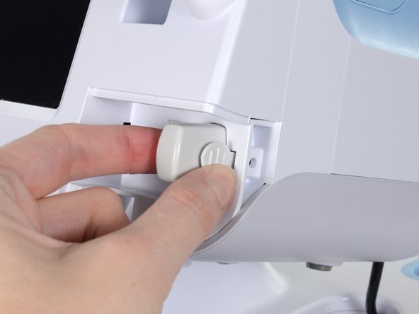
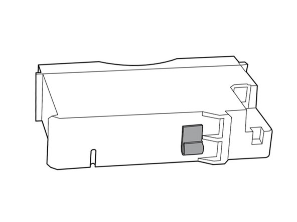
    • Remove the cover of the temperature module by pressing the tab and sliding the cover to the right.

  6. Questo passaggio è privo di traduzione. Aiuta a tradurlo

    : passo 6, immagine 1 di 3 : passo 6, immagine 2 di 3 : passo 6, immagine 3 di 3
    • Depress the spring tab on the temperature probe cable connector and withdraw it from the probe port.

  7. Questo passaggio è privo di traduzione. Aiuta a tradurlo

    : passo 7, immagine 1 di 1
    • Remove the flathead screw on the USB networking door.

    • Loosen the captive Phillips #2 screw securing the monitor to the stand.

  8. Questo passaggio è privo di traduzione. Aiuta a tradurlo

    : passo 8, immagine 1 di 1
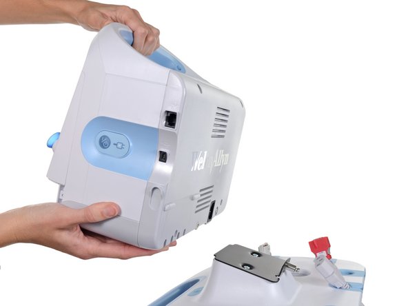
    • Holding the monitor securely, open the USB networking door.

    • You may have to lift the monitor slightly to allow the door to swing out from the stand mount.

  9. Questo passaggio è privo di traduzione. Aiuta a tradurlo

    : passo 9, immagine 1 di 2 : passo 9, immagine 2 di 2
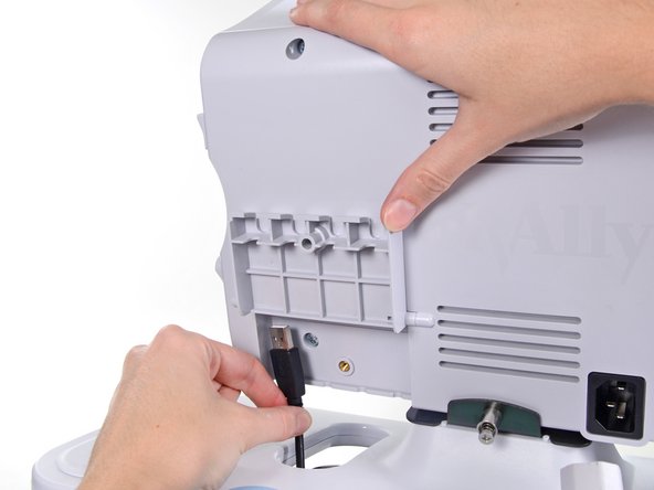
    • Detach any accessory USB cables from USB ports on the monitor.

  10. Questo passaggio è privo di traduzione. Aiuta a tradurlo

    : passo 10, immagine 1 di 3 : passo 10, immagine 2 di 3 : passo 10, immagine 3 di 3
    • Slide the monitor off of the stand tray.

  11. Questo passaggio è privo di traduzione. Aiuta a tradurlo

    : passo 11, immagine 1 di 3 : passo 11, immagine 2 di 3 : passo 11, immagine 3 di 3
    • Place the monitor upside down on a clean surface.

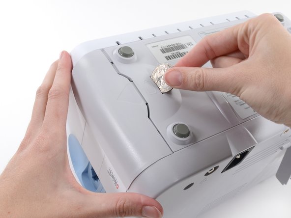
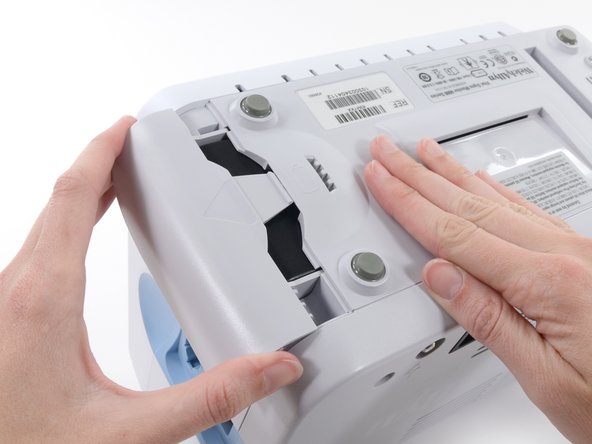
    • Insert a coin into the slot and push to open.

    • Choose a coin that fits comfortably into the slot.

    • Remove the battery cover.

  12. Questo passaggio è privo di traduzione. Aiuta a tradurlo

    : passo 12, immagine 1 di 3 : passo 12, immagine 2 di 3 : passo 12, immagine 3 di 3
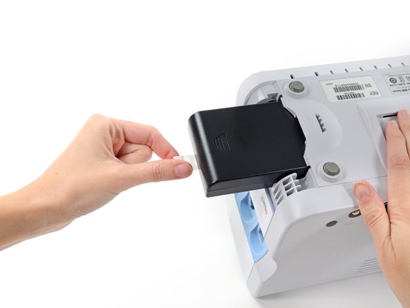
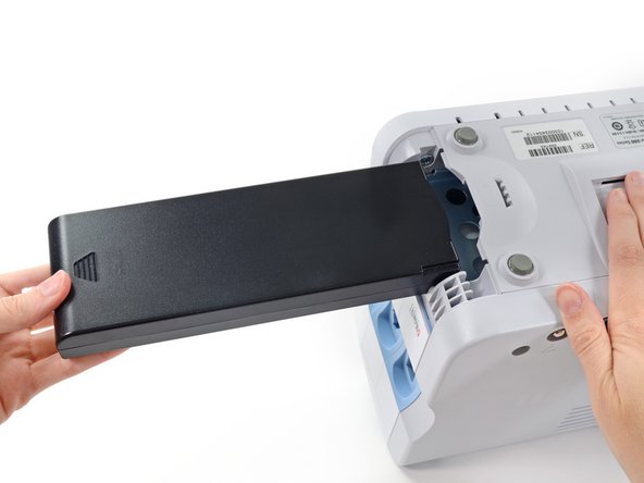
    • Use the plastic label to remove the battery from its recess.

  13. Questo passaggio è privo di traduzione. Aiuta a tradurlo

    : passo 13, immagine 1 di 2 : passo 13, immagine 2 di 2
    • Open the communications door to access the lower left-hand rear housing screw.

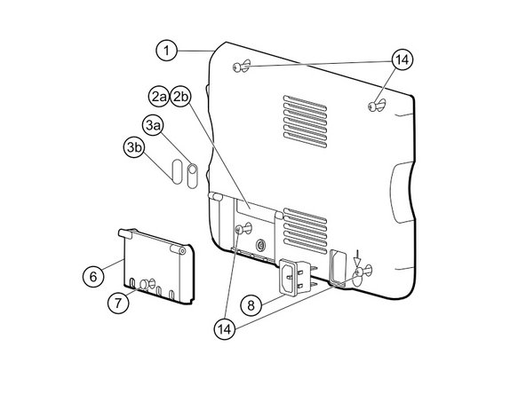
    • Remove the four Phillips #2 screws (labeled 14 in the service manual) from the rear housing.

  14. Questo passaggio è privo di traduzione. Aiuta a tradurlo

    : passo 14, immagine 1 di 2 : passo 14, immagine 2 di 2
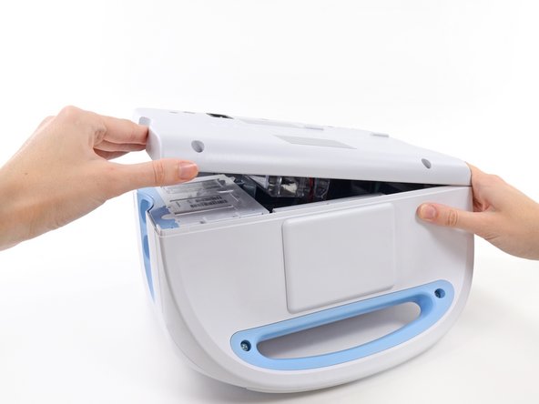
    • With the handle/alert bar facing you, begin to lift the rear housing from the left side, holding the right side securely.

    • Do not attempt to separate the rear housing from the monitor, it is still attached with several cables.

  15. Questo passaggio è privo di traduzione. Aiuta a tradurlo

    : passo 15, immagine 1 di 1
    • Support the rear housing while you disconnect the cables in the following steps.

  16. Questo passaggio è privo di traduzione. Aiuta a tradurlo

    : passo 16, immagine 1 di 3 : passo 16, immagine 2 di 3 : passo 16, immagine 3 di 3
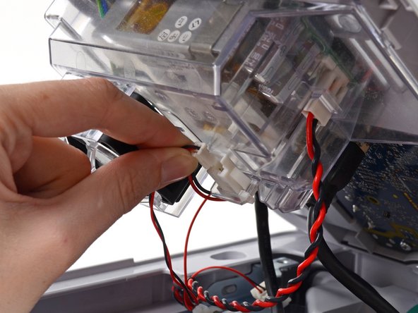
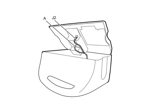
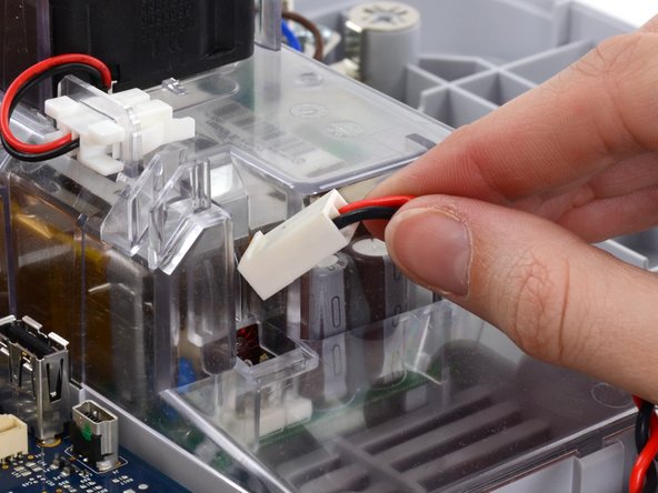
    • Disconnect the fan cable (labeled connector A in the service manual) from its socket in the power supply.

  17. Questo passaggio è privo di traduzione. Aiuta a tradurlo

    : passo 17, immagine 1 di 3 : passo 17, immagine 2 di 3 : passo 17, immagine 3 di 3
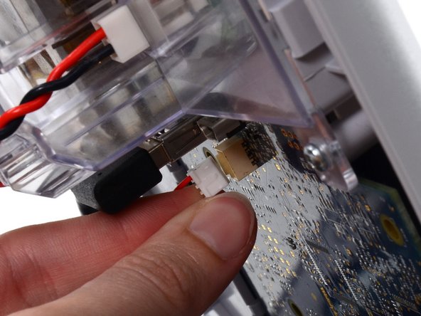
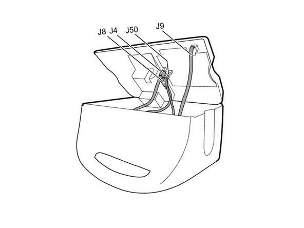
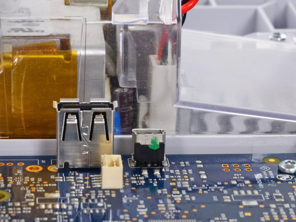
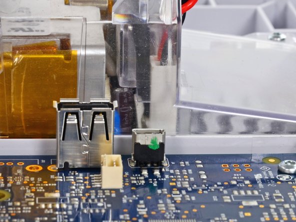
    • Unplug the small USB connector from its socket (labeled J4 in the service manual).

  18. Questo passaggio è privo di traduzione. Aiuta a tradurlo

    : passo 18, immagine 1 di 3 : passo 18, immagine 2 di 3 : passo 18, immagine 3 di 3
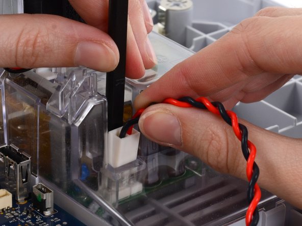
    • Disconnect the communications power cable from its socket (labeled J50 in the service manual).

    • Only pull on the connector itself and not the socket. This connection is very tight, work the connector slowly and gently.

  19. Questo passaggio è privo di traduzione. Aiuta a tradurlo

    : passo 19, immagine 1 di 3 : passo 19, immagine 2 di 3 : passo 19, immagine 3 di 3
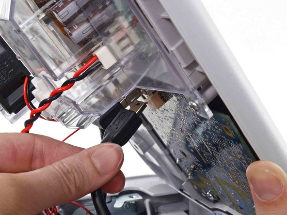
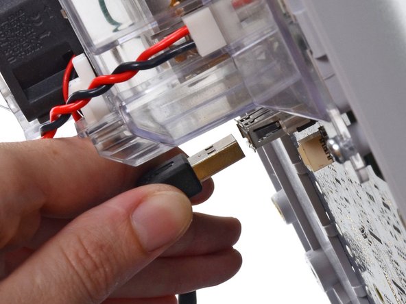
    • Unplug the large USB connector from its socket (labeled J8 in the service manual).

  20. Questo passaggio è privo di traduzione. Aiuta a tradurlo

    : passo 20, immagine 1 di 3 : passo 20, immagine 2 di 3 : passo 20, immagine 3 di 3
    • Press the tab on the ethernet cable and unplug it from its socket (labeled J9 in the service manual).

  21. Questo passaggio è privo di traduzione. Aiuta a tradurlo

    : passo 21, immagine 1 di 1
    • The following connector requires two hands to disconnect. Flip the rear case over, and lay it on its back to gain access to the power supply cable.

  22. Questo passaggio è privo di traduzione. Aiuta a tradurlo

    : passo 22, immagine 1 di 3 : passo 22, immagine 2 di 3 : passo 22, immagine 3 di 3
    • The power supply cable is secured by an interlocking connector that must be held open to unplug the connector.

    • Insert the flat end of a spudger down into the power supply cover between the socket clip and the power supply connector.

  23. Questo passaggio è privo di traduzione. Aiuta a tradurlo

    : passo 23, immagine 1 di 3 : passo 23, immagine 2 di 3 : passo 23, immagine 3 di 3
    • Grasp the power supply cable firmly and lift both it and the spudger from the channel in the power supply housing to unplug the connector.

  24. Questo passaggio è privo di traduzione. Aiuta a tradurlo

    : passo 24, immagine 1 di 3 : passo 24, immagine 2 di 3 : passo 24, immagine 3 di 3
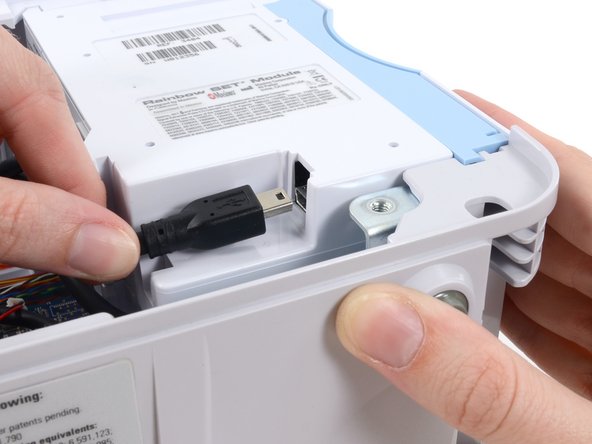
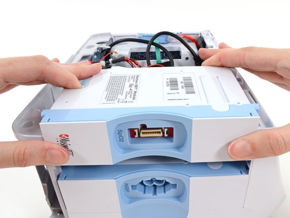
    • Disconnect the USB cable from the module.

    • For the extended chassis: Disconnect the two USB cables from the module.

  25. Questo passaggio è privo di traduzione. Aiuta a tradurlo

    : passo 25, immagine 1 di 3 : passo 25, immagine 2 di 3 : passo 25, immagine 3 di 3
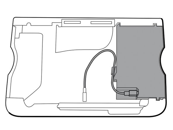
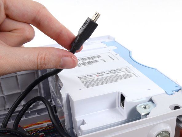
    • Remove the USB cable from the retaining clip on the module.

  26. Questo passaggio è privo di traduzione. Aiuta a tradurlo

    : passo 26, immagine 1 di 3 : passo 26, immagine 2 di 3 : passo 26, immagine 3 di 3
    • Slide the module out of the case.

    • Repeat the above procedure to remove any additional modules from the chassis.

    • During reassembly, install the module closest to the display first.

    • Reinsert modules into the housing with the serial number label facing up.

Linea Traguardo

Altre 3 persone hanno completato questa guida.

Sam Goldheart

Membro da: 10/18/12

465.783 Reputazione

538 Guide realizzate

Team

iFixit Membro di iFixit

Staff

135 Membri

16.817 Guide realizzate

0 Commenti

Aggiungi Commento

Visualizza Statistiche:

Ultime 24 Ore: 1

Ultimi 7 Giorni: 1

Ultimi 30 Giorni: 3

Tutti i Tempi: 946