Questa versione può contenere modifiche errate. Passa all'ultima istantanea verificata.
Cosa ti serve
-
Questo passaggio è privo di traduzione. Aiuta a tradurlo
-
Turn the laptop over.
-
Slide back the left lock, and you should hear a click when it is successfully locked back in.
-
-
Questo passaggio è privo di traduzione. Aiuta a tradurlo
-
Rotate the laptop 180 degrees so that the battery is near you.
-
Hold back the spring slide and pull the battery out.
-
-
Questo passaggio è privo di traduzione. Aiuta a tradurlo
-
Situate the laptop so that it is open and the display is facing you.
-
Use the plastic opening tool to pry the black plastic insert upward. The insert can be found at the top of the keyboard.
-
Once the insert is loose, carefully remove it from the device.
-
-
Questo passaggio è privo di traduzione. Aiuta a tradurlo
-
Using #1 Phillips Screwdriver, remove both of the 5 mm screws that are located beneath the insert.
-
-
Questo passaggio è privo di traduzione. Aiuta a tradurlo
-
Use the plastic opening tool to begin removing the keys off of the device.
-
-
Questo passaggio è privo di traduzione. Aiuta a tradurlo
-
Lift up the gate on the ZIF socket to release the ribbon.
-
Ease the ribbon connecting the keyboard to the motherboard out of the ZIF socket.
-
-
Questo passaggio è privo di traduzione. Aiuta a tradurlo
-
With the keyboard removed, locate the marked screws.
-
Remove the marked, 5mm screws using the #1 Phillips Screwdriver.
-
-
-
Questo passaggio è privo di traduzione. Aiuta a tradurlo
-
In the opening above the mouse pad, use the plastic opening tool to push up the black gate of the ZIF socket.
-
Remove the ribbon from the ZIF socket.
-
-
Questo passaggio è privo di traduzione. Aiuta a tradurlo
-
Locate the wide opening at the top near the screen.
-
Use the plastic opening tool to open the black ZIF socket.
-
Remove the blue ribbon.
-
-
Questo passaggio è privo di traduzione. Aiuta a tradurlo
-
Remove the three, 3 mm screws using the #1 Phillips Screwdriver.
-
-
Questo passaggio è privo di traduzione. Aiuta a tradurlo
-
Grasp the power cable with your tweezers and remove it from the wireless antenna.
-
-
Questo passaggio è privo di traduzione. Aiuta a tradurlo
-
Locate and remove both the white and black antenna leads with the tweezers.
-
-
Questo passaggio è privo di traduzione. Aiuta a tradurlo
-
Remove screws for back assembly.
-
11 x F5 (5 mm #1 Phillips)
-
6 x F2 (2 mm #0 Phillips)
-
4 x F8 (8 mm #1 Phillips)
-
1 x F3 (3 mm #1 Phillips
-
-
Questo passaggio è privo di traduzione. Aiuta a tradurlo
-
Use the plastic opening tool to release the back panel from the laptop.
-
-
Questo passaggio è privo di traduzione. Aiuta a tradurlo
-
Use the plastic opening tool to separate the top faceplate.
-
Carefully lift the faceplate off of the base by sliding the plastic opening tool around the outside of the device. You'll hear clicks as you do this.
-
-
Questo passaggio è privo di traduzione. Aiuta a tradurlo
-
Lift the back panel and carefully disconnect the main power cable.
-
-
Questo passaggio è privo di traduzione. Aiuta a tradurlo
-
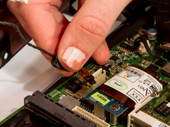
Remove the black signal cable attached at the blue circuit board.
-
-
Questo passaggio è privo di traduzione. Aiuta a tradurlo
-
Remove auxiliary power cable attached to the blue board at the back of the laptop.
-
-
Questo passaggio è privo di traduzione. Aiuta a tradurlo
-
Remove the fan mounting screws with a #1 Phillips Screwdriver.
-
-
Questo passaggio è privo di traduzione. Aiuta a tradurlo
-
Locate and remove the heat sink mounting screws using a #1 Phillips Screwdriver.
-
-
Questo passaggio è privo di traduzione. Aiuta a tradurlo
-
Carefully lift the fan and heat sink assembly.
-
Detach the fan power cable from the motherboard with your fingers by squeezing the white plastic connector and wiggling gently from side to side.
-
There will be a grey goop between the copper heat piping and the back of the processor, (indicated in pink). This is thermal paste and allows heat to flow properly.
-


Annulla: non ho completato questa guida.
Altre 4 persone hanno completato questa guida.
Team

Cal Poly, Team 7-8, Maness Winter 2013 Membro di Cal Poly, Team 7-8, Maness Winter 2013
CPSU-MANESS-W13S7G8
4 Membri
8 Guide realizzate