Questa versione può contenere modifiche errate. Passa all'ultima istantanea verificata.
Cosa ti serve
-
Questo passaggio è privo di traduzione. Aiuta a tradurlo
-
Remove the four Torx T5 screws from the back panel.
-
-
Questo passaggio è privo di traduzione. Aiuta a tradurlo
-
Wedge a spudger in between the front and back panel.
-
Apply leverage downwards to the spudger in order to remove the back panel.
-
-
Questo passaggio è privo di traduzione. Aiuta a tradurlo
-
Slide the battery out from under the brown wire-tape.
-
Be careful of the wires still connected to the other end of the battery. Do not pull or damage may occur.
-
-
Questo passaggio è privo di traduzione. Aiuta a tradurlo
-
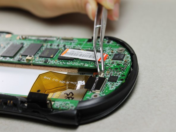
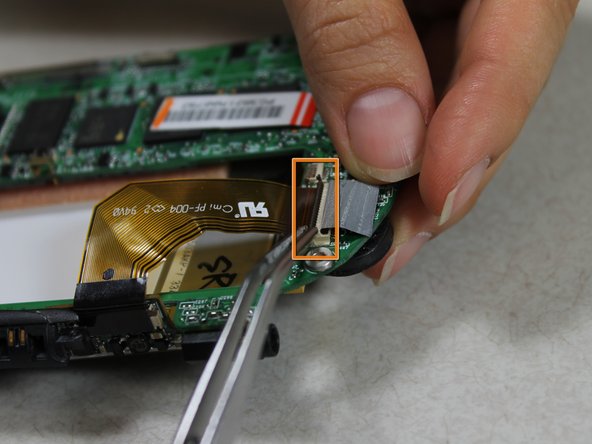
Slowly pull the white plug from its receptor. Grasp its sides firmly with a pair of tweezers and gently wiggle from side to side.
-
-
Questo passaggio è privo di traduzione. Aiuta a tradurlo
-
Unscrew the 2 Philips #00 screws on each end of the motherboard.
-
-
-
Questo passaggio è privo di traduzione. Aiuta a tradurlo
-
Pull off the black memory card slot piece with tweezers.
-
-
Questo passaggio è privo di traduzione. Aiuta a tradurlo
-
Unscrew the 2 Philips #00 screws on each side of the charging port.
-
-
Questo passaggio è privo di traduzione. Aiuta a tradurlo
-
Disconnect 2 brown wire-tape ends from each end of the motherboard. Gently pull straight out with tweezers.
-
-
Questo passaggio è privo di traduzione. Aiuta a tradurlo
-
Pull the motherboard and screen component diagonally up and left away from the auxiliary port entrance to remove.
-
-
Questo passaggio è privo di traduzione. Aiuta a tradurlo
-
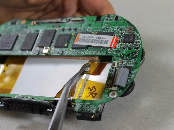
Disconnect the 2 brown wire-tape ends from the left side of the battery slot on the motherboard using tweezers.
-
-
Questo passaggio è privo di traduzione. Aiuta a tradurlo
-
Disconnect the large brown wire-tape from the motherboard.
-
Peel the black tape back from the wire-tape using tweezers.
-
Lift the black, hinged, plastic lock with tweezers to release the wire-tape.
-
The screen and motherboard components can now be separated from each other.
-
-
Questo passaggio è privo di traduzione. Aiuta a tradurlo
-
Unscrew the 2 Philips #00 screws from the bottom edge of the screen component.
-
-
Questo passaggio è privo di traduzione. Aiuta a tradurlo
-
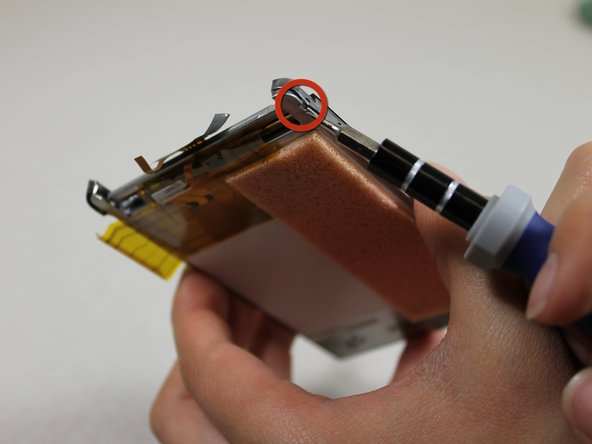
Take off the brown wire-tape from the small circuit board component.
-
Lift up so that the black plastic hinge piece swings open and the tape can be removed.
-
-
Questo passaggio è privo di traduzione. Aiuta a tradurlo
-
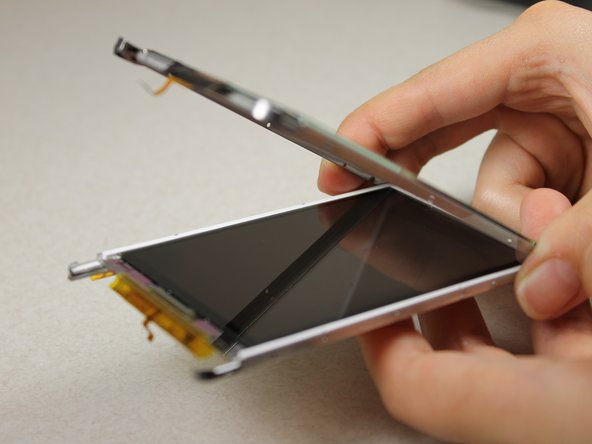
Use a Slot SL1.5 screwdriver to pry the touchscreen shell from the display component using the 4 slots around the entire component
-


Team

Cal Poly, Team 10-33, Amido Winter 2012 Membro di Cal Poly, Team 10-33, Amido Winter 2012
CPSU-AMIDO-W12S10G33
4 Membri
10 Guide realizzate