Salta al contenuto principale
Unisciti alla Community delle riparazioni - Crea un account

Stratitec S5202A Snap-in Circuit Breaker Replacement

Cosa ti serve

  1. Stratitec S5202A Snap-in Circuit Breaker Replacement, Snap-in Circuit Breaker: passo 1, immagine 1 di 1
    • Place the power strip on a level surface with the bottom facing up.

    Chiedi a FixBot

    Aggiungi Commento

  2. Stratitec S5202A Snap-in Circuit Breaker Replacement: passo 2, immagine 1 di 1
    • Remove the nine screws from the bottom plate using an IfixIt bit driver and the bit labeled PH1.

    Chiedi a FixBot

    Aggiungi Commento

  3. Stratitec S5202A Snap-in Circuit Breaker Replacement: passo 3, immagine 1 di 1
    • Remove the lower plate to expose the internal components.

    Chiedi a FixBot

    Aggiungi Commento

  4. Stratitec S5202A Snap-in Circuit Breaker Replacement: passo 4, immagine 1 di 2 Stratitec S5202A Snap-in Circuit Breaker Replacement: passo 4, immagine 2 di 2
    • The soldering tools will be hot, as will the solder when melted. Avoid contact with skin.

    • Solder fumes are toxic, avoid inhaling.

    • Turn on the solder station to the highest temperature setting and wait for it to heat.

    • Each solder station is different and some many only have an on/off switch with no temperature setting.

    • It may take up to ten minutes for the solder station to heat completely.

    • The easiest way to be sure the solder iron is hot enough is to touch the solder to the iron and see if it melts.

    Chiedi a FixBot

    Aggiungi Commento

  5. Stratitec S5202A Snap-in Circuit Breaker Replacement: passo 5, immagine 1 di 2 Stratitec S5202A Snap-in Circuit Breaker Replacement: passo 5, immagine 2 di 2
    • Locate the power switch leads and apply solder iron tip to wire 1.

    • Waiting for the solder to completely melt may take up to a minute or two.

    • Do not pull on the wire until the solder on both the lead and the wire is completely melted.

    Chiedi a FixBot

    Aggiungi Commento

  6. Stratitec S5202A Snap-in Circuit Breaker Replacement: passo 6, immagine 1 di 1
    • Once the solder has melted on the switch, use a pair of flat-head pliers to remove the wire.

    • In some cases it may be necessary to cut the tips of the wire off in order to free the wire.

    Chiedi a FixBot

    Aggiungi Commento

  7. Stratitec S5202A Snap-in Circuit Breaker Replacement: passo 7, immagine 1 di 1
    • Repeat steps 5 and 6 for wire two.

    Chiedi a FixBot

    Aggiungi Commento

  8. Stratitec S5202A Snap-in Circuit Breaker Replacement: passo 8, immagine 1 di 1
    • Loosen the power switch by pushing on the plastic side tabs located inside the power strip case.

    • If you can't get the tabs to release, use a pair of flat-heat pliers and push down on one tab at a time.

    • There are two tabs on each side of the switch.

    Chiedi a FixBot

    Aggiungi Commento

  9. Stratitec S5202A Snap-in Circuit Breaker Replacement: passo 9, immagine 1 di 2 Stratitec S5202A Snap-in Circuit Breaker Replacement: passo 9, immagine 2 di 2
    • Carefully remove the unsoldered power switch component.

    Chiedi a FixBot

    Aggiungi Commento

  10. Stratitec S5202A Snap-in Circuit Breaker Replacement: passo 10, immagine 1 di 3 Stratitec S5202A Snap-in Circuit Breaker Replacement: passo 10, immagine 2 di 3 Stratitec S5202A Snap-in Circuit Breaker Replacement: passo 10, immagine 3 di 3
    • Replace the old switch component with the new SS-001.

    • Snap in the circuit breaker component by pushing the switch down until the tabs lock into place.

    • You should be able to hear the tabs snap into place.

    Chiedi a FixBot

    Aggiungi Commento

  11. Stratitec S5202A Snap-in Circuit Breaker Replacement: passo 11, immagine 1 di 1
    • Apply new solder onto the iron tip.

    Chiedi a FixBot

    Aggiungi Commento

  12. Stratitec S5202A Snap-in Circuit Breaker Replacement: passo 12, immagine 1 di 1
    • Solder wire 1 onto the power switch tab.

    • If necessary apply extra solder to the metal pin until the wire is connected.

    • If you forget which wire goes to which tab just be sure that your switch orientation is the same as the picture shown. Once you are sure it is in the correct way, the wires simply stay on their respective sides. The left wire goes with the left pin and the right wire goes with the right pin.

    Chiedi a FixBot

    Aggiungi Commento

  13. Stratitec S5202A Snap-in Circuit Breaker Replacement: passo 13, immagine 1 di 2 Stratitec S5202A Snap-in Circuit Breaker Replacement: passo 13, immagine 2 di 2
    • Repeat steps 11 and 12 for wire 2.

    Chiedi a FixBot

    Aggiungi Commento

  14. Stratitec S5202A Snap-in Circuit Breaker Replacement: passo 14, immagine 1 di 1
    • Hold wire down with pliers until solder cools and sets.

    • If needed add more solder to wire/lead connection point.

    Chiedi a FixBot

    Aggiungi Commento

  15. Stratitec S5202A Snap-in Circuit Breaker Replacement: passo 15, immagine 1 di 1
    • Test power strip using an Ohmmeter by touching both solder joints while in off position.

    • When the switch is in the off position the circuit should be “broken” and in turn show a resistance.

    • Even if the resistance is small like the 2Ωs pictured here, it still means the switch is doing its job.

    Chiedi a FixBot

    Aggiungi Commento

  16. Stratitec S5202A Snap-in Circuit Breaker Replacement: passo 16, immagine 1 di 1
    • Repeat step 15 with the power switch in the on position.

    • While the switch is in the on position the circuit should be open and there should be no resistance between the two pins.

    Chiedi a FixBot

    Aggiungi Commento

  17. Stratitec S5202A Snap-in Circuit Breaker Replacement: passo 17, immagine 1 di 1
    • Repeat steps 2-3 in reverse order for reassembly.

    Chiedi a FixBot

    Aggiungi Commento

Conclusione

To reassemble your device, follow these instructions in reverse order.

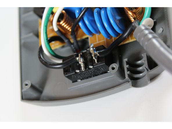
Now that you are finished, you have the satisfaction of repairing something broken as well as cutting down on electronic waste. If there are problems such as: the switch not turning on, no voltage connectivity, or if the Ohmmeter does not give the appropriate readings in steps 15 and 16, you may be lacking the appropriate amount of solder for your wiring. To fix this, reapply the solder to the joints where the wires connect to the circuit breaker. Since surge protectors are a growing need with more electronics being utilized, this guide will help you ensure your surge protector is well maintained and ready to protect your electronics.

Annulla: non ho completato questa guida.

Un'altra persona ha completato questa guida.

rainbentrott

Membro da: 09/21/15

101 Reputazione

Una guida realizzata

Team

0Commenti sulla guida

Aggiungi Commento

Visualizza statistiche:

Ultime 24 ore: 1

Ultimi 7 giorni: 19

Ultimi 30 giorni: 50

Tutti i Tempi: 1,306