Introduzione
Segui questa guida per sostituire il gruppo schermo su un Samsung Galaxy Note9.
Cosa ti serve
-
-
Premi in basso sulla S Pen finché non fa click.
-
Rilascia la S Pen e uscirà da sola.
-
Rimuovi la S Pen.
-
-
-
Inserisci uno strumento per espellere la scheda SIM per nel foro del vassoio della scheda SIM.
-
Premi per espellere il vassoio della scheda SIM.
-
-
-
Spegni il tuo telefono prima di iniziare lo smontaggio.
-
Usa un asciugacapelli, una pistola termica, o prepara un iOpener e appoggialo al bordo destro sul retro del telefono per circa un minuto per ammorbidire l'adesivo sottostante.
If using an iOpener it will need to be fully heated and set on for at least 5 minutes. You’ll know the phone is hot enough when its almost too hot to touch.
Just came here to say exactly that. The instructions should be amended to state that: "Get it fully hot and leave it there for at least three minutes solid."
-
-
-
Fai aderire una ventosa al vetro posteriore.
-
Solleva la ventosa per creare una fessura tra il pannello posteriore in vetro e la cornice del telefono.
-
Infila un plettro di apertura nella fessura.
It takes so much heat that it is concerning that damage might be caused to the internal parts. It is difficult to heat the glue, pull the case apart and insert the pick at same time. May need some more pointers to handle these situations first, to prevent possible damage. Also what about the glue that is heated and then cooled before opening? Does it run inside and cause greater adhesion after it cools? Another thing, the handling may cause the phone to turn back on while working to separate. Don't know that that is of concern.
-
-
-
Ricorda che c'è più adesivo sotto il bordo superiore e attorno alla cornice della fotocamera che sul resto del telefono.
-
Taglia con molta attenzione sul bordo sinistro vicino al sensore impronte digitali perché c'è il rischio di danneggiare il cavo a nastro sottostante.
It's extremely easy to crack the back glass when nearing and rounding the corners. It's probably a good idea to soften the adhesive with heat as you go.
Step 5 is NOT "cut through the adhesive", that's steps 5-10. Step 5 is "Begin the careful process of cutting through the adhesive, starting at the right side where you already softened it. Proceed carefully, slowly, and warmly through the following steps."
These comments are spot-on. I never break a phone, and I cracked the back glass following the instructions without seeing these comments first. Heat the back much more than you think you need and go super, super slow.
-
-
-
Iniziando dal centro, taglia l'adesivo sotto tutto il bordo destro con un plettro di apertura.
-
-
-
Lascia un plettro sotto l'angolo in alto a destra.
-
Usa un altro plettro per tagliare l'adesivo sotto l'angolo in basso a destra.
-
Lascia anche questo plettro sotto l'angolo appena tagliato.
There seems to be a lot of glue at the bottom, I broke the glass as I was cutting past the charging port - not sure if it was already fractured or just not enough heat (I used Sellotape so it didn't break up into pieces!)
I think LOTS of heat & patience is the key!
Be very careful around the corners and bottom (probably top too, but I didn't have a problem there). Make sure you've cut in far enough down the side first (go in about 1cm) but less round the corners and work in slowly.
-
-
-
Usa un asciugacapelli, una pistola termica, o prepara un iOpener e appoggialo sul bordo sinistro del pannello posteriore per circa un minuto per ammorbidire l'adesivo sottostante.
If using an iOpener it will need to be fully heated and set on for at least 5 minutes. You’ll know the phone is hot enough when its almost too hot to touch.
-
-
-
Usando il plettro infilato, taglia attentamente l'adesivo sotto l'angolo superiore sinistro del pannello posteriore.
-
Infine, taglia l'adesivo sotto il bordo superiore del telefono.
Be VERY patient as you slide the opening picks around the periphery of the glass, and use heat very liberally. Make sure the smooth, clear aspect of the iOpener is against the glass, not the rough black portion.
-
-
-
Separa prima il bordo destro della cover posteriore.
-
Inclina il pannello facendo perno sul bordo sinistro per accedere al cavo a nastro del sensore impronte digitali.
Thought I'd done something wrong here as there wasn't a cable attached to the back - the fingerprint reader hadn't come away with the back, but had stayed with the phone.
Exactly the same experience. Made life a little easier.
Happened to me as well.
-
-
-
Usa la punta di uno spudger per far leva sul cavo a nastro del sensore impronte digitali e scollegarlo dalla sua presa.
-
-
-
Rimuovi la cover posteriore.
-
Usa delle pinzette per rimuovere qualsiasi adesivo rimasto sul telaio del telefono. Quindi pulisci le aree dove era presente l'adesivo con dell'alcool isopropilico (>90%) e un panno senza lanugine per preparare la superficie al nuovo adesivo.
-
Applica attentamente il nuovo adesivo al vetro posteriore. Quindi allinea un bordo della cover al bordo del telaio del telefono e premilo con decisione sul telefono.
I am installing a new backplate (this is my first repair; I was CERTAIN that I would crack the back glass, and I was NOT wrong) but I’m not sure how tweezers are meant to remove gooey adhesive! I simply used the blue plastic pry tool as a scraper and gently rolled up the goo. Maybe the glue is different because I have a refurbished phone? That may also explain why I had so much trouble with Step 1. Hope that this helps!
-
-
-
Passo 15 Rimuovi il frame intermedio superiore
Attenzione: i passaggi 15-18 provengono da una guida contrassegnata come in corso.
-
Usa un cacciavite a croce Phillips per rimuovere le nove viti da 4 mm che tengono in posizione il frame intermedio.
There are two more screws on the bottom right corner of the little side frame that the Qi plate is glued to. I took those out as it put less stress on it.
It helps to hold the fine tweezers with your non-dominant hand to support the screw heads and ensure they come straight out; you can also gently lift as you unscrew.
-
-
-
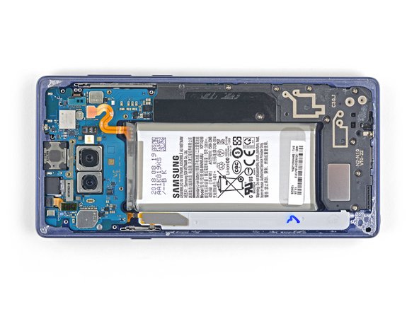
Usa la punta di uno spudger per scollegare il cavo a nastro arancione che collega la batteria alla scheda madre.
-
-
-
Rimuovi le nove viti a croce Phillips da 4 mm dalla copertura in plastica di fianco alla batteria.
-
-
-
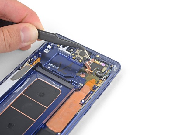
Usa la punta di uno spudger per fare leva sul connettore della fotocamera frontale e rimuoverlo dalla sua presa.
-
Usa delle pinzette per rimuovere la fotocamera frontale.
-
-
-
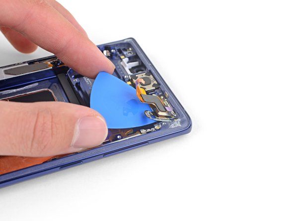
Usa la punta di uno spudger per disconnettere lo scanner dell'iride dalla scheda madre.
-
Usa delle pinzette per rimuovere lo scanner dell'iride.
-
-
-
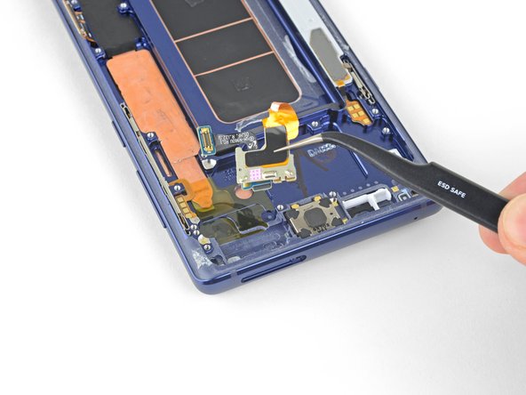
Usa la parte piatta di uno spudger per fare leva sul connettore dei sensori anteriori e rimuoverlo dalla sua presa.
-
-
-
Usa la parte piatta di uno spudger per disconnettere il cavo dello schermo dalla scheda madre.
-
-
-
Usa l'estremità piatta di uno spudger per disconnettere il gruppo di ricarica dalla scheda madre.
These screws are supposed to be 3.2 mm because when I took out these screws, they were shorter than the ones you take out first
-
-
-
Rimuovi la vite a croce Phillips da 3,2 mm dal jack delle cuffie.
-
-
-
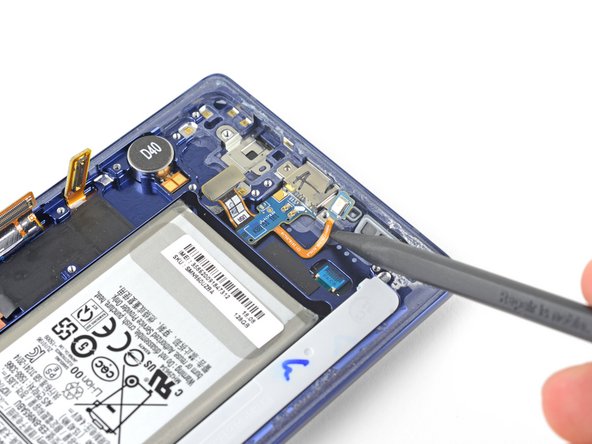
Inserisci la punta di uno spudger nell'incavo di fianco ai punti di contatto del jack cuffie.
-
Solleva la scheda dei contatti per liberarla dall'adesivo sottostante.
-
-
-
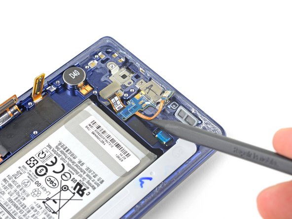
Rimuovi le due viti a croce Phillips da 3,2 mm dal gruppo di ricarica.
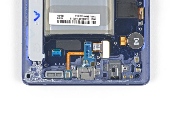
Please add a step that mentions the round item labeled “D40”. It, similarly to the headphone jack, is tediously removed by adding some isopropyl alcohol to the groove above/under it and then sliding a spudger or tweezers into the same groove. Slowly wiggle it with your prod while the isopropyl alcohol does its job.
This is necessary If your new display assembly does not include the vibration motor (labeled D40). The pointed end of a spudger may not be small enough to get leverage under it, so use angled tweezers if you have to.
-
-
-
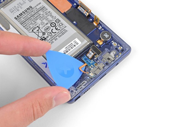
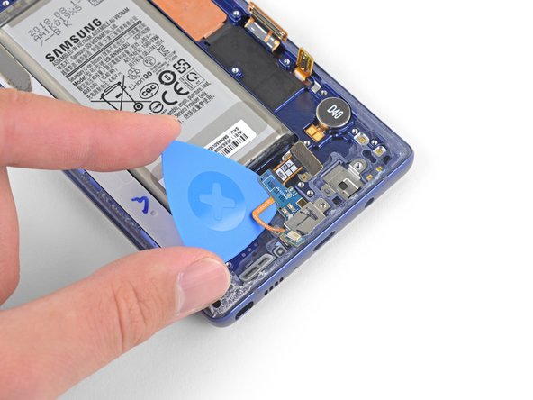
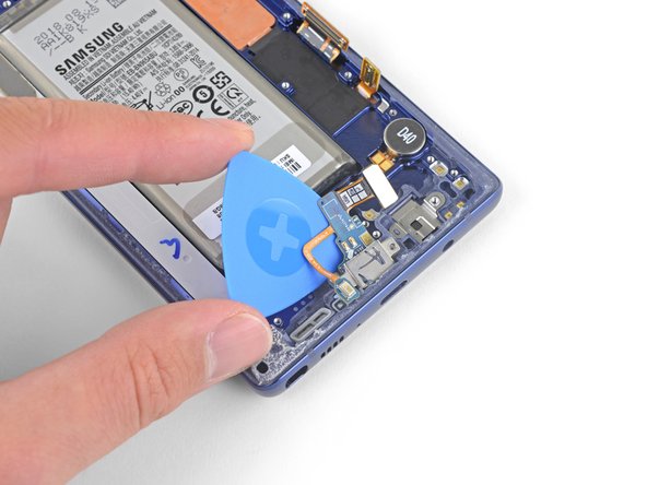
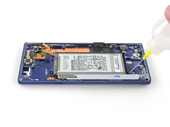
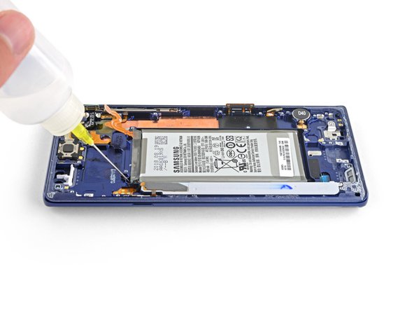
Applica qualche goccia di alcool isopropilico ad alta concentrazione (>90%) nell'alloggio della batteria, lungo il lato inferiore e l'angolo in alto a sinistra della batteria.
-
Aspetta un paio di minuti per far sì che l'alcool ammorbidisca l'adesivo sotto la batteria.
-
Tieni il telefono ad angoli diversi per aiutare l'alcool a scorrere sotto la batteria.
-
-
-
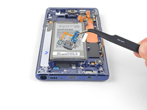
Usa delle pinzette per rimuovere la lamina di rame adesiva.
-
Smetti di sollevare la lamina una volta che hai raggiunto i sensori anteriori.
-
-
-
Usa le pinzette per rimuovere il gruppo dei sensori anteriori.
Buen día, excelente tutorial...sigan con ese mismo interes...Bendiciones para todo el grupo.
Desde Santa Cruz, Bolivia.
-


Per rimontare il dispositivo, segui le istruzioni in ordine inverso.
Porta i tuoi rifiuti elettronici a un riciclatore certificato R2 o e-Stewards.
La riparazione non è andata come previsto? Dai un'occhiata alla nostra comunità Risposte per trovare aiuto.
Confronta la tua parte di ricambio con quella originale: potrebbe essere necessario il trasferimento di alcuni componenti o la rimozione di protezioni adesive dalla nuova parte prima di installarla.
Annulla: non ho completato questa guida.
Altre 46 persone hanno completato questa guida.
Un ringraziamento speciale a questi traduttori:
100%


Questi traduttori ci stanno aiutando ad aggiustare il mondo! Vuoi partecipare?
Inizia a tradurre ›

15 Commenti
Make sure you transfer over the vibration motor if the new frame does not have it… didn’t realize my replacement didn’t have it until I put the glass back on :/
Thank you for pointing this out! I almost missed it! I wish this guide showed how to put it back together instead of just saying “okay now do it again but backwards.” Anyway, I appreciate this comment right here haha.
The guide assumes that you have a new display unit containing all the parts that are left after the last step (display, front glass, screen, cooling system, vibration motor and so on.)
Since replacement parts vary from seller to seller, you’ll have to compare yours to the original and transfer any remaining components. This guide was written for the display assembly that we were selling at the time.
When transferring other components such as the vibration motor just be sure to use the same methods as with similar components. Work slowly, always use heat or ≥90% isopropyl alcohol to soften adhesives, and search the internet for more information as necessary.
But what about the actual replacement of the display screen? The instructions stops at removing the front sensor array
Because it is an OLED screen the entire assembly has to be replaced. If the guide is followed and the part was purchased from iFixit, once the front sensor array is removed you can begin working backwards transferring all components into the new display assembly. Unfortunately replacing the screen from the front is not possible. If you purchase the part from somewhere other than iFixit you may need to transfer additional components.
The guide does not explain how to glue the front and back together once everything is put back together.
Do I have to buy a specific glue or does the new part have pre-applied glue and do I need heat to activate?
Thanks
The new part most likely won’t have pre-installed adhesive. This generic perimeter adhesive guide for Samsung Galaxy phones will help!
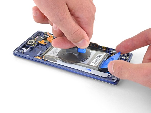
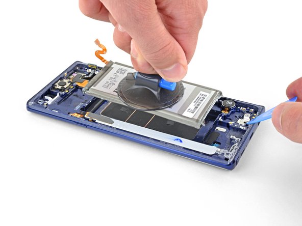
Any suggestions on getting the suction cup to stick to the battery? I cant seem to get mine to hold.
I just flooded the battery space with rubbing alcohol and let it sit for a minute. Then the battery more or less lifted out. If you still think you need it a smaller suction cup or even dental floss to run under the battery may help.
It was very informative and clear. Thank You.
Hello! I would ask, but the display is the same for version 128 or 512gb, right?
I have never had a digitizer not power on. Is it just a bad digitizer or what? I also brought a new battery.
The gasket and adhesive kit came with a great set of components. However it's not clear when and where they are put. Would be nice if iFixit had notes about these for reassembly.