Introduzione
La scheda madre integra tutta la potenza di elaborazione del tuo dispositivo e si collega ai vari componenti all'interno del dispositivo. Come con qualsiasi riparazione di questo tipo, fai attenzione quando disconnetti dalla scheda madre questi componenti.
Cosa ti serve
-
-
Spegni il telefono.
-
Incunea il tuo strumento di apertura in plastica nella giunzione tra le due facce del dispositivo. Fai leva e apri un lato alla volta.
-
-
-
Usa anche le dita attorno alla giunzione tra il dispositivo e la cover posteriore. Usa il tuo strumento di apertura in plastica o le dita per separare ciascun lato fino a staccare completamente tra loro il dispositivo e la cover posteriore.
I did two of these. The first was a WIFI model that the earphone plug had become intermittant (just needed to resolder the connections.) The second an LTE version that the battery had gone bad and swelled to about 3 times the size.
The swollen battery had pushed the glass free of the upper mount, and made the entire thing extremely tight.
The WIFI one came apart easily like described.
The LTE one (with the swollen battery) required a lot more care and a lot more force/damage to get into the gap between the two plastic pieces. (I did the wifi one first, so I could easily tell the difference.
So depending on your situation...it may not be easy to separate the pieces...but remmber, the thin glass is sitting on one piece of plastic, the gap is between that piece of plastic and the back panel...a darker shiny black plastic is the top piece, a slightly lighter duller black plastic is the back panel...of course the glass is ALSO black...so good luck.
-
-
-
Inserisci lo strumento di apertura in plastica sotto il bordo laterale del connettore della batteria e fai leva delicatamente per scollegarlo.
We moved this step to be fist, thanks for the edit!
-
-
-
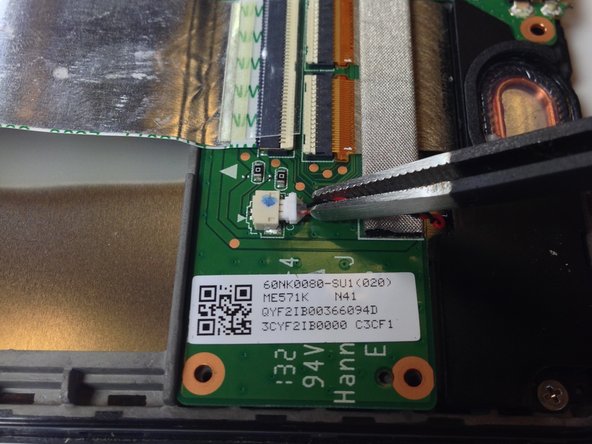
Usa l'estremità piatta di uno spudger o le unghie per far scattare l'aletta protettiva trasparente sullo zoccolo ZIF del cavo piatto.
-
Con l'estremità piatta di uno spudger o le unghie, solleva la porzione sottile del connettore (dal lato opposto a dove si inserisce il cavo) per liberare il cavo dal suo zoccolo.
-
Sfila il cavo dallo zoccolo ZIF.
Flip up on the WHITE part, facing away from the cable. I sort of struggled with this part, but fortunately didn't do any serious damage.
This is the correct way to do it. Flipping up the white part is what you have to do. I tried flipping up the black part and some of it broke off.
Ryan -
I found that I had to flip up on the black part here. I broke a section of the white trying to flip it up.
This comment saved me on this step. Indeed the secret is to flip up the black part of the connector, located opposite the side where the cable inserts.
This is wrong, these comments should be deleted so as to not confuse more people.
It's possible there's more than one color variation in production on these Nexus 7 ZIF sockets. To complicate matters, it looks like the guide's original author/photographer may have simply yanked the ribbon cable out without opening the socket, so there's very little visual clue here as to which is the right section to flip up. Based on these photos, I'd say Hannah's tip is probably correct—you want to flip up the thinner portion of the socket, opposite the cable (regardless of its color scheme). If someone who has successfully completed this step could supply a better photo, that would be super helpful!
I revised the text so there's no long any mention of the coloration of the socket.
This was my first time with this kind of ZIF socket and found these instructions/pictures ambiguous. In hindsight I see what was being described (actually used the replacement daughterboard as my guide). May I suggest this phrasing:
The ZIF clamp hinges on the side opposite of where the cable in inserted. Using the flat end of a spudger or your fingernail, flip the thin portion of the connector up and away from the insertion side of the connector.
Correction of Charles' Oct comment: The ZIF clamp hinges on the same side as the cable is inserted, the side towards the battery. The cable runs over the battery and into the thick connector, with contacts both on the side closest to the battery and on the side away from the battery. Beyond the contacts on the side away from the battery is the thin part to be lifted. Using the flat end of a spudger or your fingernail, flip the thin portion of the connector up and towards the insertion side of the connector. You can leverage gently against the big copper-covered area on the side away from the battery, in lifting the thin (white in the current picture) part of the connector.
You can leverage gently against the big copper-covered area on the side away from the battery, in lifting the thin (white in the current picture) part of the connector, using a motion similar to the described in step 5 below for removing the orange ribbon connector.
some better macro photos of the zif socket would help a lot, in closed and open states
Please make the pictures clearer as Iain Lennon said. I too was a fool to not read the comments and broke the connector off of the motherboard.
Ha.
So one side of the cable has a white strip connector, and the other side has a black strip connector. (both comments above are correct, depending on which side you are looking at)
The side in the photo has a black connector strip that needs to be opened. It is the long small strip of plastic on the _opposite_ side of the connection point, to the cable.
It clicks up into the air, like on a hinge.
The cable then pulls out, without any resistance.
Having totally destroyed the ZIF connector I can now say that the WHITE portion is hinged and the BLACK portion is not. Both parts are extremely fragile. The photographs are really useless.
exactly ……..
esykas -
This shouldn’t be the first cable to disconnect. Disconnect the battery cable first. Always remove power first!
Good catch @hobohax0r, we rearranged the steps to help fix that!
I have added a photo of the socket in the open state. Also looking at the comments above it seems that the confusion is due to the fact that this cable is connected to a similarly looking connector on the other side, where the colors are reversed. It may be worth to point this out and tell that the connector the guide is talking about is located near the heatsinks
I tried to take some pictures of the way the sockets worked on mine (2013 Wi-Fi (Flo)), but considering hardware variations, I’m not sure if this applies to every Nexus 7 (or even every Flo)
Just to follow up, much later… if you see white, you should see a small notch. lift there.
Look very carefully at the second photo and see the white “flap” has been opened, pointing at you.
Whichever color, it takes NO REAL EFFORT to flip them back. No need to force anything at this micro level.
-
-
-
Ora che i due cavi piatti principali sono scollegati, ripiegali e tienili lontano con le dita, oppure sistemaci sopra le pinzette o un altro oggetto leggero per tenerle discoste.
-
-
-
-
Usa il cacciavite a croce Phillips #0 per rimuovere le quattro viti a croce cromate Phillips #0 da 3 mm disposte attorno all'alloggiamento della batteria.
There are 6 screws on mine. One at the top and the other directly across from that on the other side of the battery at the bottom. These two screws are covered with a small adhesive sticker that says “seal". Those stickers need to be removed so the Phillips screwdriver can be inserted to remove them.
-
-
-
Rimuovi la batteria dal dispositivo esercitando una certa pressione alla base della batteria e quindi sollevandola.
If your replacement battery doesn’t have the metal battery tray included (like mine came) be aware you’ll have to CAREFULLY pry the old battery out of the metal tray. It has some pretty strong glue holding it in, but prying on it slowly and carefully should get it free without bending up the metal tray. There should be enough glue residue left in the tray to hold the new battery in, at least until you get the tablet back together.
Thank you for the very helpful comment - I was facing the same issue!
You probably should add that the battery is held in the tray with some glue strips. It took a bit to carefully remove the battery from the tray without bending the tray too much. Also, the replacement battery I had was slightly smaller than the OEM battery. When putting back together make sure you place the battery in the tray so the battery is close enough to the battery connector and you can reconnect the battery without pulling on the connector wires.
-
-
-
Rimuovi il sigillo grigio che copre la vite superiore centrale sulla scheda figlia.
I couldn't get a grasp on the sticker enough to peel it off, so just punched through it with the screwdriver. I don't know the point of removing the sticker, since the warranty is voided anyway by either time or the mere act of disassembly.
How come the battery is still in place in the picture? I couldn't get the battery out until I'd removed another 3 screws...1 on the daughterboard (step 11) and 2 on the motherboard (step 16).
There actually is no need to remove the daughter board and everything like that. Mother and daughterbord can be taken off at the same time, together with speakers and kept together by the WIFI cables, if you only need replacing the screen
This guide is still value-for-the-money if you need all the other tricky little details
-
-
-
Con un cacciavite a croce Phillips #0, svita le cinque viti nere da 2 mm tutto attorno al bordo della scheda figlia.
-
Usa lo stesso cacciavite Phillips #0 per rimuovere due viti cromate da 3 mm da ciascuna lato della micro USB.
Is there a reason you suggested removing the screws at this point? I found it to be more of a hassle having the board moving around as I did the next several disconnects. Unless there's a good reason, I would suggest leaving the screws in until the foam and the connectors have been detached.
-
-
-
Usa l'estremità piatta di uno spudger o un'unghia per sbloccare con delicatezza le due alette di bloccaggio di ciascuno zoccolo ZIF.
Flip up on the WHITE part, facing away from the cable. I sort of struggled with this part, but fortunately didn't do any serious damage.
-
-
-
Usa delle pinzette per staccare lo sticker adesivo dalla vite centrale più vicina alla batteria.
I couldn't get a grasp on the sticker enough to peel it off, so just punched through it with the screwdriver. I don't know the point of removing the sticker, since the warranty is voided anyway by either time or the mere act of disassembly.
the stickers are probably put there for insulating purposes. i have found that discarding them has no bearing on nexus' operation.
-
-
-
Usa l'estremità piatta di uno spudger oppure un'unghia per sollevare l'aletta di bloccaggio della connessione ZIF del cavo a nastro.
The front panel assembly I got from iFixit didn't have this ribbon cable for power and volume, so I had to peel it off the old one. To remove it, work the spudger underneath and gently loosen it from the adhesive. There should be enough residual adhesive to stick it in place on the replacement panel assembly.
your amendments are much appreciated. definitely helpful. THank YOU!
I also had to remove the old ribbon cable here. I used a credit card to slide behind the adhesive.
-
-
-
Usando un cacciavite con testa a croce Phillips #0, rimuovi le tre viti nere da 2 mm che fissano il bordo interno della scheda madre.
-
Con lo stesso cacciavite, rimuovi le cinque viti cromate da 3 mm che bloccano il bordo esterno della scheda madre.
-
-
-
Solleva con cura la scheda madre tenendola per i bordi e rimuovila dall'involucro del tablet.
Careful when comparing to this picture. Actually, the camera which can be seen on the left oh the housing in this picture is connected to the board.
Removing the camera is necessary, as it is impossible (with any tool I have, anyway) to reconnect the camera to the motherboard while it is still in the housing. However, doing so was quite a pain on my machine as it not only did not "lift out of the tablet with the motherboard", but it also was stuck in there so tightly I wondered if it might be glued. I needed to spend several minutes gently prying it out with pliers.
I would add that it’s imperative to loosen the camera from its housing before attempting to remove the motherboard. The two are connected via another very short ribbon cable with zif connector. Trying to pull the motherboard out with the camera still stuck to the front could damage the cable/connector. In my mind it’s safer for both to come out together while still connected.
Also, see that conductive strip in the lower right corner of the first picture with the brownish tape on the metal backplane? Many replacements do not come with that. If you look on the back of the motherboard there is a copper strip that matches this conductive strip. It connects this copper strip on the motherboard to the metal backplane of the touch screen and helps the touchscreen work properly. It doesn’t peal off easily so work at it carefully.
-


Per rimontare il tuo dispositivo, segui queste istruzioni in ordine inverso.
Per rimontare il tuo dispositivo, segui queste istruzioni in ordine inverso.
Annulla: non ho completato questa guida.
Altre 34 persone hanno completato questa guida.
Un ringraziamento speciale a questi traduttori:
100%

albertob ci sta aiutando ad aggiustare il mondo! Vuoi partecipare?
Inizia a tradurre ›
Team

Cal Poly, Team 20-16, Maness Winter 2015 Membro di Cal Poly, Team 20-16, Maness Winter 2015
CPSU-MANESS-W15S20G16
4 Membri
24 Guide realizzate
15 Commenti
Very great guide on the teardown for swapping the motherboard. I have 2 questions if you wouldn't mind clearing up.
1. When you remove the back cover from the screen, is it glued into place or does it use small snaps to hold onto the device? How hard is it to reattach the back cover?
2. After buying a new motherboard for installation will I need to flash it with bios/firmware/OS to get it working or will it come as a ready-to-go motherboard?
Thanks for your help!
Great guide, excellent pictures, helped me resurrect my Nexus stuck on the Google screen. Thank you!
However, it should be emphasized that steps 10-15 are completely unnecessary and should be skipped if you are only looking to replace the motherboard.
Agree on skipping steps 10-15 for motherboard replacement. The daughterboard was not in the way at all.
Great guide and good instructions. I was able to swap out a faulty motherboard without any problems.
Two things I found that might need some addition/update on the instructions;
1) I found a #00 Phillips easier to use than the recommended #0 Phillips
2) You should probably add one more step to explain how the camera is attached with a ZIP socket to the underside of the motherboard. That would help in reconstructing the tablet in case, like me, your camera does not come up with the motherboard.
Great work and thanks for the help!
This is a wonderful guide and very easy to follow. Hats off to ifixit for speedy delivery of parts I needed to get my Nexus 7 back. Having the toolkit really made my task easy, well worth the purchase price. Thanks for the community comments, I did skip steps 10-15 and use Philips #00 and everything went well.
No need to remove camera from case, if it stays in place when lifting motherboard.
Also this guide needs better pictures, you can't tell which part of zif connectors are the hinge/flap.
Toughest part of this repair was cracking open the case to get to work.
As others suggest skip step 10-15.
I was able to replace the motherboard using this guide, thus saving my poor tablet after the original motherboard mysteriously failed. Since official repair labor + parts costs are more than the Nexus 7 is even worth, home repair was really the only option. It is very doable, but not a repair for the faint of heart. I cracked the edge of the case while removing the screen, despite spending several minutes on it, being as gentle as I could; that sucker is just stuck on there tight! Also, my camera was stuck in the front case, and it was extremely difficult to remove without damaging it (but, removing it was necessary to connect to the new motherboard).
As a final note, I'd also say that the replacement motherboard comes with the ORIGINAL version of Android for this tablet, so it was several major versions behind when first turned on. However, I skipped having to re-install all the intervening versions by connecting it to my Mac, then using ADB to install the latest version from the Google website.
The guide is very useful. Unfortunately, Ihe ZIF socket for the larger flat cable lifted off the motherboard when I tried to pry the top of the socket open when I went to remove that cable. I just ordered a new Motherboard from IFIXIT to replace the one I just broke - pretty inexpensively.
Is the Wi-Fi version mother board compatible with the LTE version? My Nexus7 died and I rather repair mine than buy a new one, and since I’ve allways used the wi-fi connection…… (sorry for my english)
Kudos for this very helpful guide. As mentioned above, steps 10-15 aren’t necessary if you’re just replacing the motherboard. The rear-facing camera may also stick to the display housing, so be careful to release and not damage the ribbon cable connected to it when lifting the motherboard out.
I had a heck of a time doing this, spent ten or twenty minutes carefully prying, and I STILL cracked the case. At least on mine, the case was held in VERY well and required prying pretty much everywhere before it would let go. The tools I bought from iFixit really helped, but still a royal pain to open.
pacmanmaster - Replica
a couple of obscure things that might help in opening:
guitar pick. get a few; they are cheap.
a prying device made for the sign industry: its called"lil' chizler". I have found that this to be the most helpful opening tool.
http://www.ebay.com/itm/like/16184595677...
also
https://www.qualitylogoproducts.com/trad...
you can use the broken screen unit to test.
Len Gorsky - Replica
Add "remove the sim tray"...
Iain Lennon - Replica
I echo the previous - a right royal pain to get the cover off! I started on the right side as seemed to be more give there… iFixit tools helped tho!
Steven Emery - Replica
Just for the sake of clarity, I would add that you need to pry between the plastic bezel and the back casing. Not between the glass and bezel. Someone had already tried on the one I worked on and part of the bezel was missing in the top right corner. Made my job easier!
The best tools for this part are definitely something like the iFixit Jimmy and their opening tool, a few guitar picks and a spudger. Not too difficult once you get the first separation.
Cool_Breeze - Replica
I managed to easily crack the screen, guess I’ll have to order a new one and “try” to put it in, in addition to the original job of replacing a dead battery on Nexus 7 2013..ahhhhhh, slow learner…
Gary Stamey - Replica
Opened the case for the first time. It took me a while to find any gaps, but I found that the easy way to begin was using your fingernail to get into the sides. The middle left and middle right seemed a lot easier to…slip a nail in compared to the rest of the case, especially the corners and the top and bottom. With a small opening on both sides I used the opening tool to increase the gaps while using a couple of guitar picks to prop up the device against the back case. With most of the sides exposed, I worked on the bottom (create opening, leave a guitar pick to keep that part open, use the opening tool to get the rest out), and the opening was pretty much complete.
So far only the corners of the back case showed small cracks and my screen was pretty much unscathed.
Nam Lam - Replica
This method worked best for me! Start opening on the middle left and right sides, then prop them open with guitar picks and use to the opening tool (carefully) prying up several times moving away from the middle towards the corners to pop off the back casing.
Frank's VR -