Questa versione può contenere modifiche errate. Passa all'ultima istantanea verificata.
Cosa ti serve
-
Questo passaggio è privo di traduzione. Aiuta a tradurlo
-
Carefully grab the edges of the laptop and flip it over to reveal the back panel.
-
The battery is located on the lower half of the back panel, and contains three 10mm flat-head screws.
-
Unscrew the three 10mm flat-head screws using a flat-head screw driver.
-
Lift the battery from the lip closest to the middle screw to remove the battery entirely.
-
-
Questo passaggio è privo di traduzione. Aiuta a tradurlo
-
The middle Phillips head screw is 10mm in length and will only fit in this thread. Unscrew the 10mm Phillips head screw and keep it separate from the other two screws in this step.
-
Unscrew the two remaining 5mm Phillips head screws on the left and right side of the hard drive bay cover.
-
Lift the panel to remove it.
-
-
Questo passaggio è privo di traduzione. Aiuta a tradurlo
-
Remove the three 5mm Phillips head screws that secure the Hard Drive bay to the back panel.
-
-
Questo passaggio è privo di traduzione. Aiuta a tradurlo
-
Remove the Hard Drive bay by gently pulling the black plastic tab away from the SATA connector.
-
-
Questo passaggio è privo di traduzione. Aiuta a tradurlo
-
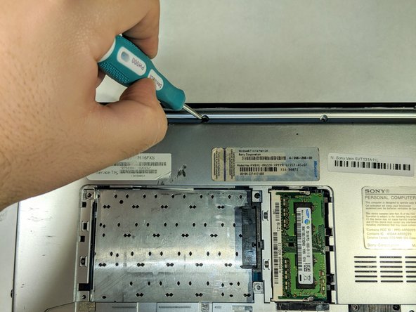
Remove the eleven 5mm in length Phillips head screws around the perimeter of the back panel of the laptop.
-
Remove the two 5mm in length Phillips head screws holding down the track pad panel to the track pad.
-
-
Questo passaggio è privo di traduzione. Aiuta a tradurlo
-
Use a prying tool, separate the back panel from the laptop.
-
-
-
Questo passaggio è privo di traduzione. Aiuta a tradurlo
-
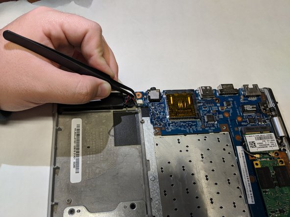
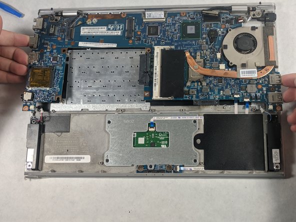
Using a pair of tweezers, remove the two cables connecting both speakers to the motherboard panel.
-
-
Questo passaggio è privo di traduzione. Aiuta a tradurlo
-
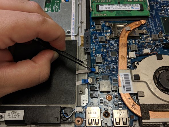
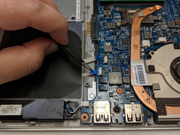
Locate the ribbon cable connecting the trackpad to the motherboard.
-
Lift the white plastic tab holding the ribbon cable in place to release it.
-
Remove the ribbon cable by pulling the blue tab away from the motherboard.
-
-
Questo passaggio è privo di traduzione. Aiuta a tradurlo
-
Locate the ribbon cable connecting the LED Array to the motherboard.
-
Lift the white plastic tab holding the ribbon cable in place to release it.
-
Remove the ribbon cable by pulling the blue tab away from the motherboard.
-
-
Questo passaggio è privo di traduzione. Aiuta a tradurlo
-
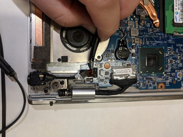
Locate the cable that connects the charging port to the motherboard.
-
Grab the head of the cable and pull up and away from motherboard to disconnect it.
-
-
Questo passaggio è privo di traduzione. Aiuta a tradurlo
-
Locate the ribbon cable connecting the keyboard to the motherboard.
-
Lift the white plastic tab up to release the keyboard ribbon cable.
-
Pull the blue tab away from the connector to remove the cable.
-
-
Questo passaggio è privo di traduzione. Aiuta a tradurlo
-
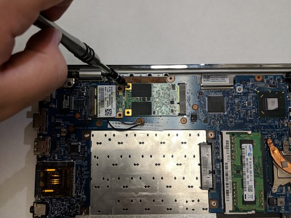
Locate the wireless network interface card (NIC) above the area where the hard drive bay sits normally.
-
Using a plastic opening tool, remove the two cable head wires connecting the NIC to the motherboard.
-
-
Questo passaggio è privo di traduzione. Aiuta a tradurlo
-
Unscrew the 5mm Phillips head screw holding the NIC to the motherboard.
-
Remove the NIC from the PCIe slot on the motherboard.
-
-
Questo passaggio è privo di traduzione. Aiuta a tradurlo
-
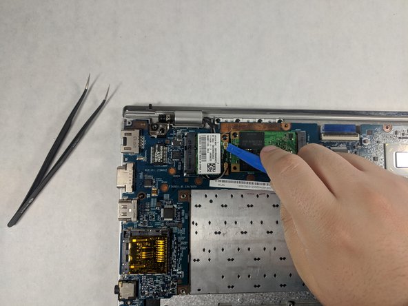
Locate the Solid State Drive (SSD) on the motherboard.
-
Unscrew the 5mm Phillips head screw securing the SSD in place on the motherboard.
-
Remove the SSD from the PCIe slot on the motherboard.
-
-
Questo passaggio è privo di traduzione. Aiuta a tradurlo
-
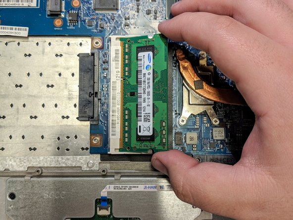
Locate the Random Access Memory (RAM) card on the motherboard.
-
Pull the two metal clips securing the RAM apart, releasing the card from the DIMM slot.
-
Remove the RAM from the motherboard, be sure to store this safely as your replacement motherboard with NOT come with a new one.
-
-
Questo passaggio è privo di traduzione. Aiuta a tradurlo
-
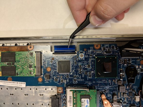
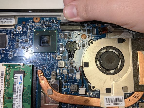
Locate the display cable connecting the keyboard to the motherboard.
-
Grab the clear plastic tab attached to the top of the connector, and pull away from the motherboard to separate it from the board.
-
-
Questo passaggio è privo di traduzione. Aiuta a tradurlo
-
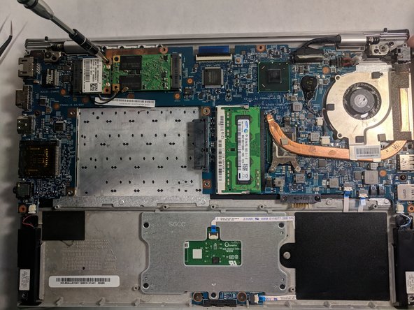
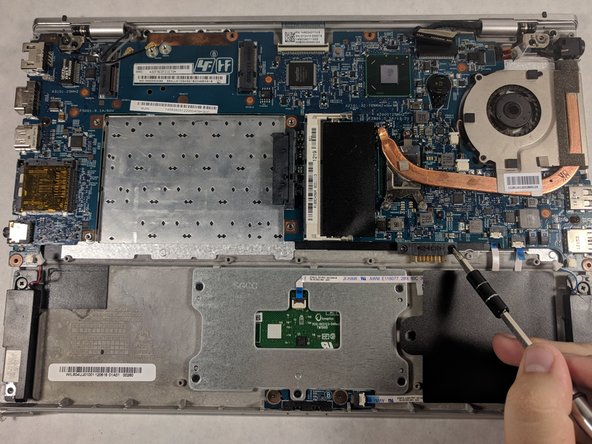
Unscrew the three 5mm Phillips head screws holding the motherboard to the laptop.
-
Grab the edges of the motherboard and lift the it slowly up and away from the back panel of the laptop.
-


Annulla: non ho completato questa guida.
Altre 3 persone hanno completato questa guida.
Team

UMass Dartmouth, Team S4-G5, Julie Fall 2017 Membro di UMass Dartmouth, Team S4-G5, Julie Fall 2017
UMASSD-JULIE-F17S4G5
3 Membri
10 Guide realizzate