Questa versione può contenere modifiche errate. Passa all'ultima istantanea verificata.
Cosa ti serve
-
Questo passaggio è privo di traduzione. Aiuta a tradurlo
-
Locate the battery door at the bottom of the camera.
-
Press down on the door and slide it back. The door will pop open.
-
-
Questo passaggio è privo di traduzione. Aiuta a tradurlo
-
Remove the battery from the door that you opened in the previous step.
-
-
Questo passaggio è privo di traduzione. Aiuta a tradurlo
-
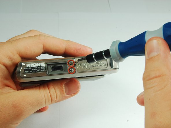
Use a PH00 screwdriver and remove the six 2.9mm screws.
-
-
Questo passaggio è privo di traduzione. Aiuta a tradurlo
-
Use hands to gently pry the front casing away from the camera.
-
-
Questo passaggio è privo di traduzione. Aiuta a tradurlo
-
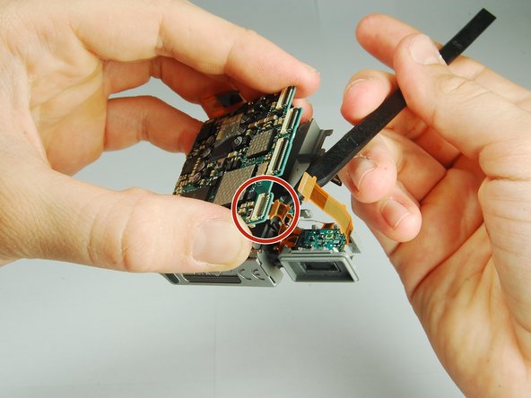
Use the tip of a spudger to flip up the tab on the ZIF connector securing the motherboard ribbon cable.
-
The second picture shows what these tabs look like in their open positions.
-
-
-
Questo passaggio è privo di traduzione. Aiuta a tradurlo
-
Carefully disengage the internal components from the casing by lifting at the bottom end and giving a gentle tug.
-
The components are still connected to the casing via cables, but they are much more maneuverable.
-
The flash module is shown on the right hand side.
-
-
Questo passaggio è privo di traduzione. Aiuta a tradurlo
-
Use the tip of a spudger to flip up the tab on the ZIF connecter securing the motherboard ribbon cable.
-
Grasp the flash module by the bottom and remove it.
-
-
Questo passaggio è privo di traduzione. Aiuta a tradurlo
-
Use tweezers to slide the white piece on the back of the back cover to the right.
-
This will dislodge the white piece, allowing you to remove it from the back cover.
-
-
Questo passaggio è privo di traduzione. Aiuta a tradurlo
-
Use the tip of a spudger to flip up the tab on the ZIF connector securing the motherboard ribbon cable.
-
Remove the ribbon cables from these two ZIF connectors.
-
-
Questo passaggio è privo di traduzione. Aiuta a tradurlo
-
Lift the motherboard assembly up and rotate it so you can easily see where the internals connect to the back cover.
-
Remove the ZIF connectors from the clamp on the left end of the top piece.
-
The motherboard assembly is now separated from the back cover.
-
-
Questo passaggio è privo di traduzione. Aiuta a tradurlo
-
Locate the screw inside the small white piece on the motherboard assembly.
-
Remove this 2.9mm screw using a PH00 screwdriver.
-
-
Questo passaggio è privo di traduzione. Aiuta a tradurlo
-
Use tweezers to remove the small white piece from the motherboard assembly.
-
-
Questo passaggio è privo di traduzione. Aiuta a tradurlo
-
Turn the motherboard assembly over.
-
Use a spudger to open the ZIF connector on the motherboard.
-
Remove the ribbon cables from the opened clip.
-
-
Questo passaggio è privo di traduzione. Aiuta a tradurlo
-
Pry the motherboard slightly apart form the motherboard assembly.
-
Disconnect the ribbon cable connecting the battery pack to the motherboard.
-
-
Questo passaggio è privo di traduzione. Aiuta a tradurlo
-
Pull the motherboard up from the battery pack and flip the motherboard assembly over.
-
Use a PH00 screwdriver to remove the 2.9mm screw connecting the speaker to the battery pack.
-