Questa versione può contenere modifiche errate. Passa all'ultima istantanea verificata.
Cosa ti serve
-
Questo passaggio è privo di traduzione. Aiuta a tradurlo
-
Flip the console over on its back.
-
Take note of your model number, in case replacement parts are needed.
-
-
Questo passaggio è privo di traduzione. Aiuta a tradurlo
-
Remove the expansion bay by applying pressure to the small clip on the expansion bay while prying it away from the console.
-
-
-
Individua e rimuovi le quattro viti nere Phillips #02 da 12 mm dai lati inferiori della console.
-
-
-
Questo passaggio è privo di traduzione. Aiuta a tradurlo
-
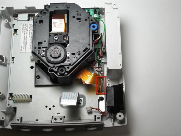
Detach the orange cable by giving it a gentle pull while wiggling the cable back and forth until it loosens from the logic board.
-
-
Questo passaggio è privo di traduzione. Aiuta a tradurlo
-
Detach the cables by gently pulling the three GD-ROM cables to remove them from the logic board.
-
-
Questo passaggio è privo di traduzione. Aiuta a tradurlo
-
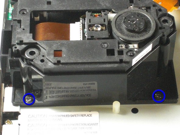
Remove the two black 12mm Philips #02 screws located on the left side of the GD-ROM bracket.
-
-
Questo passaggio è privo di traduzione. Aiuta a tradurlo
-
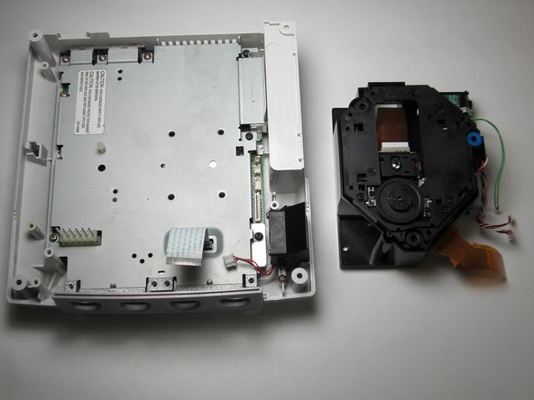
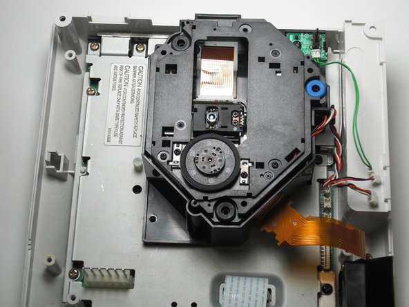
Remove the GD-ROM by gently lifting it from its base.
-
-
Questo passaggio è privo di traduzione. Aiuta a tradurlo
-
Replace the bad GD-ROM drive with a functional one.
-
-
Questo passaggio è privo di traduzione. Aiuta a tradurlo
-
Secure the new GD-ROM drive to the console with the Philips #2 screws.
-
-
Questo passaggio è privo di traduzione. Aiuta a tradurlo
-
Connect the three GD-ROM cables to the logic board.
-
Connect the GD-ROM data ribbon to the logic board.
-


Annulla: non ho completato questa guida.
Altre 10 persone hanno completato questa guida.
Team

Cal Poly, Team 5-1, Regan Fall 2009 Membro di Cal Poly, Team 5-1, Regan Fall 2009
CPSU-REGAN-F09S5G1
5 Membri
21 Guide realizzate
Un commento
If only it was that simple Sega screwed U.K gamers over with the fact we have to buy totally new consoles due to the wires of the disk drive being soldered in rather than clipped in.