Questa versione può contenere modifiche errate. Passa all'ultima istantanea verificata.
Cosa ti serve
-
-
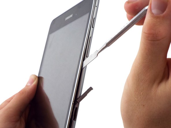
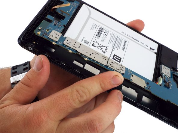
Individua lo slot della memory card, e partendo dalla sua parte superiore, utilizza l'estremità piatta dello spudger piccolo per separare la scocca inferiore dal resto del dispositivo.
-
-
-
Dopo aver usato il piccolo spudger in metallo, usa quello medio per rimuovere completamente la scocca posteriore. Puoi farlo facendo scivolare lo spudger in metallo lungo tutto il perimetro del dispositivo, utilizzando come punto di partenza la parte superiore dello slot della memory card.
-
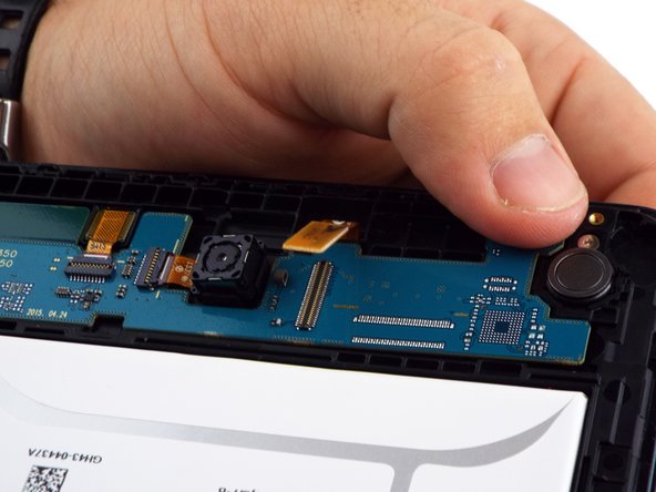
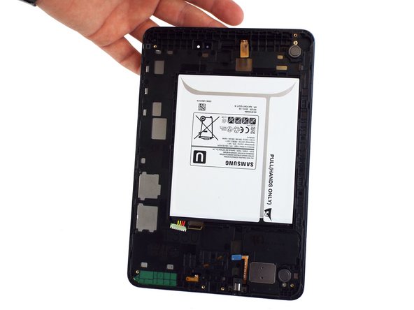
La seconda immagine mostra la parte interna del dispositivo non appena avrai rimosso la scocca posteriore.
-
-
-
Questo passaggio è privo di traduzione. Aiuta a tradurlo
-
Use a spudger to lift up and release the press-fit display cable connector from the motherboard.
-
-
Questo passaggio è privo di traduzione. Aiuta a tradurlo
-
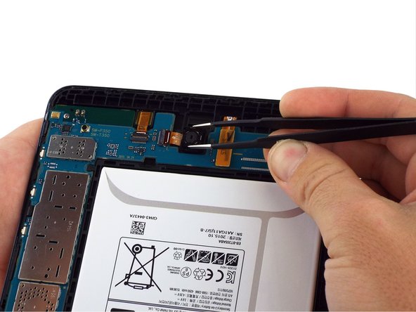
Use a spudger to lift up and release the ZIF connector; gently pull the rear facing camera ribbon cable free.
-
Use a pair of tweezers to gently secure the camera and lift it out of the frame.
-
-
Questo passaggio è privo di traduzione. Aiuta a tradurlo
-
Use a spudger to flip the front-facing camera ZIF connector up; gently pull the ribbon cable free.
-
Use tweezers to gently remove the front facing camera from the frame.
-
-
Questo passaggio è privo di traduzione. Aiuta a tradurlo
-
Use the flat end of a spudger to lift up and disconnect the LCD screen press-fit connector.
-
-
Questo passaggio è privo di traduzione. Aiuta a tradurlo
-
Use the flat end of a spudger to lift up and disconnect the 3.5mm headset jack press-fit connector.
-
-
Questo passaggio è privo di traduzione. Aiuta a tradurlo
-
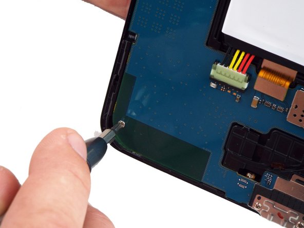
Use a PH000 screwdriver to remove the two 3 mm screws that connect the USB port shield to the midframe.
-
-
Questo passaggio è privo di traduzione. Aiuta a tradurlo
-
Use a PH000 screwdriver to remove the two 3 mm screws on the left side of the motherboard.
-
-
Questo passaggio è privo di traduzione. Aiuta a tradurlo
-
Lift the motherboard free from the power and volume button side.
-
You may use a spudger to assist in gently lifting the motherboard up from the button side.
-
A small plastic bracket secures the motherboard to the frame; lift the motherboard from the power and volume button side first, and slide away from the bracket.
-


Annulla: non ho completato questa guida.
Altre 13 persone hanno completato questa guida.


3 Commenti
Where is the rest of this guide? Just stops after removing motherboard :[
It appears that it is intended to remove all parts from the case (battery and motherboard) and install them in a new body with a good screen attached.
Ben D -
After removing the motherboard, I continued with disassembly by following the iFixit guide for the Digitizer removal.
( Samsung Galaxy Tab A Digitizer Replacement )
After removing the glass/digitizer, I was able to remove the LCD relatively easy by pushing it through the gaps on the back end of the frame. It appeared to not have any adhesive holding it in place. I was replacing the LCD and the digitizer in my case so I was I bit more careless with the removal of those components. I did place a bit of adhesive on the new LCD replacement and everything fit back snuggly.