Questa versione può contenere modifiche errate. Passa all'ultima istantanea verificata.
Cosa ti serve
-
Questo passaggio è privo di traduzione. Aiuta a tradurlo
-
Grasp the cap of the stylus and remove it from its slot in the midframe.
-
-
Questo passaggio è privo di traduzione. Aiuta a tradurlo
-
Pry with a plastic opening tool, or your fingernail, in the divot to the right of the rear-facing camera, near the volume rocker.
-
-
Questo passaggio è privo di traduzione. Aiuta a tradurlo
-
Lift and remove the rear case from the phone.
-
-
Questo passaggio è privo di traduzione. Aiuta a tradurlo
-
Insert your finger in the notch of the battery compartment.
-
Press the battery toward the rear facing camera while pulling outward.
-
-
Questo passaggio è privo di traduzione. Aiuta a tradurlo
-
Use the flat end of a spudger, or your fingernail, to press the microSD card slightly deeper into its slot until you hear a click.
-
After the click, release the card and it will pop out of its slot.
-
-
Questo passaggio è privo di traduzione. Aiuta a tradurlo
-
Remove the microSD card from its slot in the midframe.
-
-
Questo passaggio è privo di traduzione. Aiuta a tradurlo
-
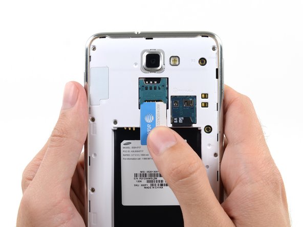
Use a plastic opening tool, or your fingernail, to push the SIM card out of its compartment.
-
-
Questo passaggio è privo di traduzione. Aiuta a tradurlo
-
Slide the SIM card out the rest of the way with your thumb and remove it from the device.
-
-
-
Questo passaggio è privo di traduzione. Aiuta a tradurlo
-
Remove the nine 3.4 mm Phillips #00 screws securing the midframe to the display assembly.
-
-
Questo passaggio è privo di traduzione. Aiuta a tradurlo
-
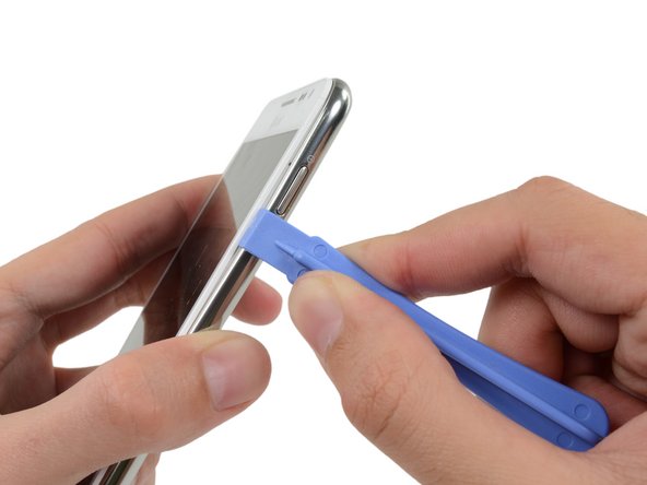
Insert your plastic opening tool to the left of the power button between the midframe and the front panel assembly and pry.
-
-
Questo passaggio è privo di traduzione. Aiuta a tradurlo
-
Slide the plastic opening tool down the seam.
-
-
Questo passaggio è privo di traduzione. Aiuta a tradurlo
-
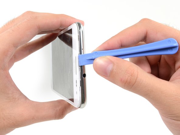
Insert your plastic opening tool to the left of the headphone jack between the midframe and the display assembly.
-
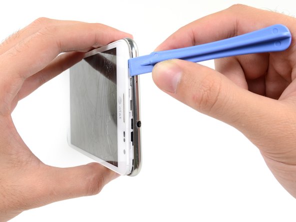
Slide the opening tool along the top edge of the phone.
-
Continue to run the plastic opening tool around the perimeter of the phone until the midframe is separated.
-
-
Questo passaggio è privo di traduzione. Aiuta a tradurlo
-
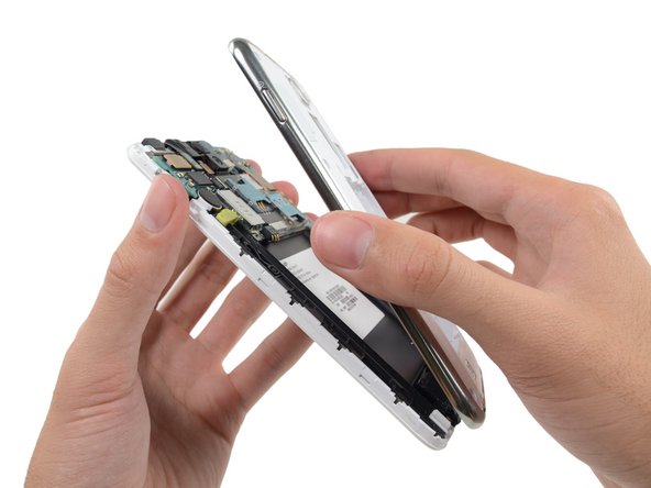
Remove the midframe from the display assembly.
-
-
Questo passaggio è privo di traduzione. Aiuta a tradurlo
-
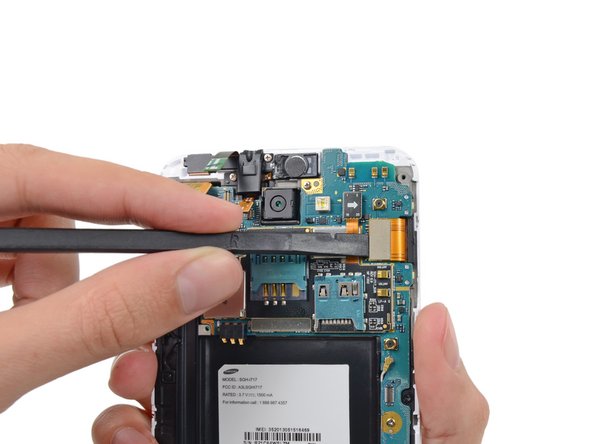
Use the flat end of a spudger to carefully disconnect the display cable connector.
-
-
Questo passaggio è privo di traduzione. Aiuta a tradurlo
-
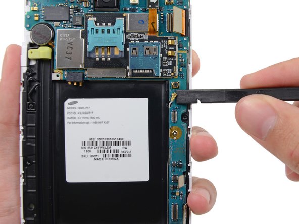
Use a spudger to disconnect the front-facing camera assembly cable connector.
-
Disconnect the headphone jack/earpiece speaker assembly cable connector.
-
Disconnect the digitizer cable connector.
-
-
Questo passaggio è privo di traduzione. Aiuta a tradurlo
-
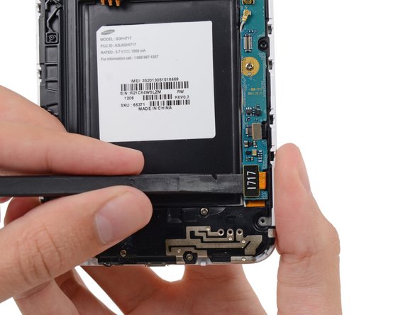
Disconnect the soft button cable connector with the flat end of a spudger.
-
Use a spudger to disconnect the USB board cable connector.
-
Disconnect the antenna cable connector.
-
-
Questo passaggio è privo di traduzione. Aiuta a tradurlo
-
Remove the two 3.4 mm Phillips #00 screws securing the motherboard to the display assembly.
-
-
Questo passaggio è privo di traduzione. Aiuta a tradurlo
-
Remove the motherboard assembly from the display assembly.
-
-
Questo passaggio è privo di traduzione. Aiuta a tradurlo
-
Remove the three 3 mm Phillips #00 screws securing the speaker enclosure to the front panel assembly.
-
-
Questo passaggio è privo di traduzione. Aiuta a tradurlo
-
Lift the speaker enclosure from the display assembly.
-
-
Questo passaggio è privo di traduzione. Aiuta a tradurlo
-
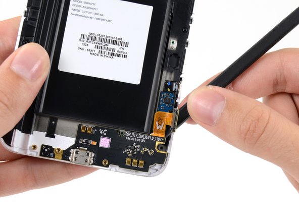
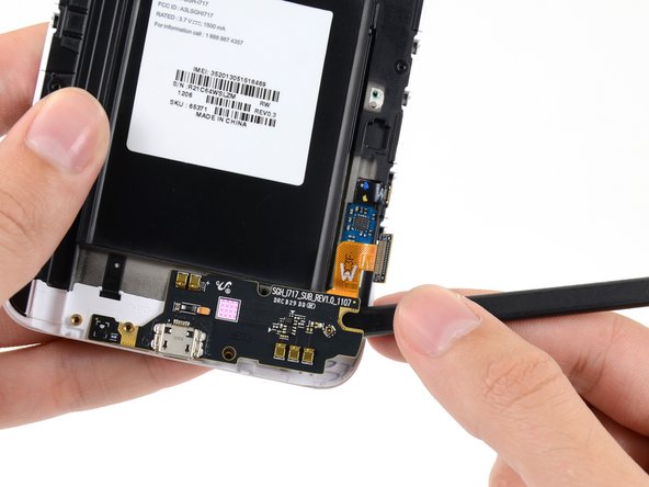
Use the tip of a spudger to disconnect the antenna cable connector from the USB board.
-
Remove the antenna cable.
-
-
Questo passaggio è privo di traduzione. Aiuta a tradurlo
-
Push the flat end of a spudger under the USB board to separate it from the display assembly.
-


Annulla: non ho completato questa guida.
Altre 51 persone hanno completato questa guida.


6 Commenti
It's not necessary to remove the motherboard (steps 17 and 18) to complete this repair. The flat flex running to the USB board can be easily slid out from under the motherboard with the motherboard still in position. Just omit steps 17 and 18 and the rest of the procedure works fine. I've done it twice.
Where in England could I buy the USB Board part?
USB board bought off ebay. Didnt need plastic opening tools, thumb nail worked easier than expected.
It's not the Galaxy Note GT-N7000!