Questa versione può contenere modifiche errate. Passa all'ultima istantanea verificata.
Cosa ti serve
-
Questo passaggio è privo di traduzione. Aiuta a tradurlo
-
Grasp the end of the stylus and remove it from its slot in the midframe.
-
-
Questo passaggio è privo di traduzione. Aiuta a tradurlo
-
Pry with a plastic opening tool, or your fingernail, in the divot to the left of the rear-facing camera, near the power button.
-
-
Questo passaggio è privo di traduzione. Aiuta a tradurlo
-
Lift the rear case by the corner nearest the divot and remove it from the phone.
-
-
Questo passaggio è privo di traduzione. Aiuta a tradurlo
-
If you have an SD card inserted, use the flat end of a spudger, or your fingernail, to press the microSD card slightly deeper into its slot until you hear a click.
-
After the click, release the card and it will pop out of its slot.
-
Remove the microSD card.
-
-
Questo passaggio è privo di traduzione. Aiuta a tradurlo
-
Insert a plastic opening tool, or your finger, into the notch of the battery compartment and lift the battery upward.
-
-
Questo passaggio è privo di traduzione. Aiuta a tradurlo
-
Remove the eleven 4.0 mm Phillips #00 screws securing the midframe to the display assembly.
-
-
-
Questo passaggio è privo di traduzione. Aiuta a tradurlo
-
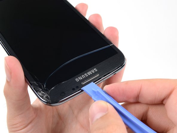
Insert your plastic opening tool between the midframe and front panel assembly on the side of the phone.
-
Slide the plastic opening tool down the seam.
-
-
Questo passaggio è privo di traduzione. Aiuta a tradurlo
-
Continue to run the plastic opening tool down the seam.
-
-
Questo passaggio è privo di traduzione. Aiuta a tradurlo
-
Carefully pry around the corner with a plastic opening tool.
-
-
Questo passaggio è privo di traduzione. Aiuta a tradurlo
-
Pry along the top of the phone with a plastic opening tool.
-
-
Questo passaggio è privo di traduzione. Aiuta a tradurlo
-
Push the plastic opening tool down to free the corner of the midframe from the display assembly.
-
-
Questo passaggio è privo di traduzione. Aiuta a tradurlo
-
Free the clips along the power button side of the phone.
-
Lastly, free the two clips along the top and bottom edge of battery compartment.
-
-
Questo passaggio è privo di traduzione. Aiuta a tradurlo
-
Lift the display assembly out of the midframe.
-
-
Questo passaggio è privo di traduzione. Aiuta a tradurlo
-
Remove the 3 mm Phillips #00 screw from the speaker enclosure.
-
-
Questo passaggio è privo di traduzione. Aiuta a tradurlo
-
Using the flat end of a spudger, disconnect the USB board cable connector.
-
Use the tip of a spudger to disconnect the antenna cable connector from the USB board.
-
-
Questo passaggio è privo di traduzione. Aiuta a tradurlo
-
Push the flat end of a spudger under the USB board to separate it from the display assembly.
-
-
Questo passaggio è privo di traduzione. Aiuta a tradurlo
-
Remove the USB board from the display assembly.
-


Annulla: non ho completato questa guida.
Altre 67 persone hanno completato questa guida.


10 Commenti
Very good tutorial of the process needed to do this repair. Sadly the one that I was trying to repair had been dropped and the circuit board right where the charge pcb attaches was physically cracked. Did not find that problem until actually removing the original part and throughly inspecting the connect area. Thank You again for an excellent tutorial and dialogue.
Excellent tutorial regarding the disassembly of the Note II and replacement if the charge circuit board. Sadly the device i have had been dropped and the main circuit board where the charge PCB plugs into it was fractured. After removal of the original charge board through inspection noted the original problem was the cracked main PCB. :( Now I have a Note II with a good case and display but damaged main circuit board.
I replaced my USB board and success. However my speakers are not working now. Someone please guide me .