Questa versione può contenere modifiche errate. Passa all'ultima istantanea verificata.
Cosa ti serve
-
Questo passaggio è privo di traduzione. Aiuta a tradurlo
-
Insert a SIM card eject tool, bit, or a straightened paperclip into the small hole in the SIM card tray.
-
Press to eject the tray.
-
-
Questo passaggio è privo di traduzione. Aiuta a tradurlo
-
Insert an opening pick between the screen and the back cover on the bottom of the phone where the charging port is located.
-
-
Questo passaggio è privo di traduzione. Aiuta a tradurlo
-
Slide the opening pick to the bottom left corner to release the clips.
-
-
Questo passaggio è privo di traduzione. Aiuta a tradurlo
-
Slide the opening pick along the left edge to the top left corner of the phone, to release the clips.
-
-
Questo passaggio è privo di traduzione. Aiuta a tradurlo
-
Slide the opening pick from the top left corner to the top right corner to release the plastic clips.
-
-
Questo passaggio è privo di traduzione. Aiuta a tradurlo
-
Slide the opening pick from the top right corner to the bottom right corner to release the remaining clips.
-
-
-
Questo passaggio è privo di traduzione. Aiuta a tradurlo
-
Remove screws from the motherboard antenna cover.
-
3 Phillips #00, 3mm length.
-
-
Questo passaggio è privo di traduzione. Aiuta a tradurlo
-
Use the tip of a spudger or tweezers to remove the antenna cover.
-
-
Questo passaggio è privo di traduzione. Aiuta a tradurlo
-
Remove screws from the motherboard cover.
-
3 Phillips #00, 3mm length
-
-
Questo passaggio è privo di traduzione. Aiuta a tradurlo
-
Use the tip of a spudger or tweezers to remove the motherboard cover.
-
-
Questo passaggio è privo di traduzione. Aiuta a tradurlo
-
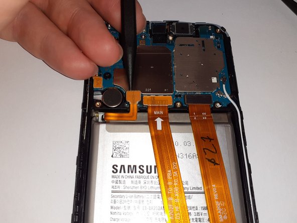
Use a spudger to disconnect the battery by prying the connector straight up from its socket.
-
-
Questo passaggio è privo di traduzione. Aiuta a tradurlo
-
Gently flex the battery connector away from its socket.
-
-
Questo passaggio è privo di traduzione. Aiuta a tradurlo
-
Remove screws from daughterboard cover.
-
7 Phillips #00, 3mm length.
-
-
Questo passaggio è privo di traduzione. Aiuta a tradurlo
-
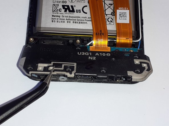
Use a pair of tweezers to lift up the bottom of the daughterboard cover to a ~30 degree angle.
-
Pull the daughterboard cover straight out, away from the phone.
-
-
Questo passaggio è privo di traduzione. Aiuta a tradurlo
-
Insert the flat end of a spudger under the interconnect flex connector, and gently pry it straight up.
-
-
Questo passaggio è privo di traduzione. Aiuta a tradurlo
-
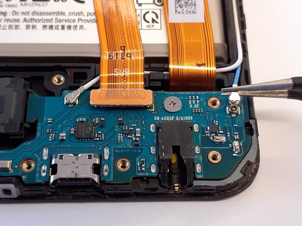
Using a pair of tweezers, gently disconnect one of the antenna connectors.
-
-
Questo passaggio è privo di traduzione. Aiuta a tradurlo
-
Using a pair of tweezers, gently disconnect the other antenna connector.
-
-
Questo passaggio è privo di traduzione. Aiuta a tradurlo
-
Remove screw from daughterboard.
-
1 Phillips #00, 2mm length.
-


Annulla: non ho completato questa guida.
Altre 12 persone hanno completato questa guida.
2 Commenti
a common issue with the A10E is the phone notifying you that you have water damage in the usb type-C port this can be fixed by replacing the daughter board which has a IC which is commonly faulty.
From where can you obtain a new daughterboard?