Questa versione può contenere modifiche errate. Passa all'ultima istantanea verificata.
Cosa ti serve
-
-
Disponi la 3DS al contrario. Rimuovi eventuali schede di gioco, cuffie, cavi di ricarica, stilo e qualsiasi altra cosa potrebbe essere connessa al dispositivo.
-
-
-
Usando un cacciavite a croce JIS #0, svita le due viti nere posteriori.
My experience indicates that a JIS #1 is more appropriate here.
Same here, much more appropriate.
-
-
-
La batteria è collocato sulla parte di sinistra della 3DS - per rimuoverla, sfrutta la piccola fenditura posta in alto al centro e fai leva con uno strumento non metallico appuntito.
Also you should remove any SD card at this point
Does this battery work on a NEW 3DS XL model?
This guide is for the New 3DS XL, which is called the 2015 3DS XL here on iFixit. If you're asking about the 3DS replacement battery advertised in the iFixit store, I believe it works for both new and old models.
-
-
-
Con un cacciavite JIS #000, rimuovi le sei viti da 6 mm intorno ai bordi della cover secondaria.
I used a #00 instead it works better for a model form 2016
remove the micro Sd card or the shell wont come off and damage the Sd card reader and the connecter
-
-
-
Utilizzando una pinzetta, estrai con cautela i paracolpi in gomma situati sul lato superiore del 3DS. Rimuovendoli, si scopriranno altre due viti da 6 mm. Rimuovi anche queste viti con un JIS #000.
Can the rubber bumpers be replaced once you reassemble the 3DS? I'd really hate to have to take them out and never be able to put them back in, if I'm honest...
Yep, we were able to put them back in quite easily after repeated teardowns! If they ever refused to stay in for some reason, you could always put a little bit of something sticky on them. (I use scrapbooking tape on my laptop's bumpers.)
What happens if I strip one of these screws? How hard would into be to remove them?
very hard. i stripped 4 screws on my new 3ds xl and i haven’t been able to get them out. i even bought the precision screw extrator set and nothing the set sucked.
-
-
-
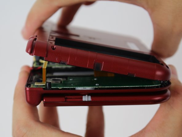
Per separare la cover posteriore, sollevala con cautela e allontanala dalle cerniere (in modo da liberare la porta per le cuffie), quindi ruotala verso le cerniere per esporre le schede dei circuiti.
I accidentally opened it and broke the ribbon cable to the r and zr buttons by accident. How do I fix it?
You have to replace the whole thing.
-
-
-
-
Con un paio di pinzette, sollevare le due spine che fissano i cavi a nastro dei pulsanti L/R/ZL/ZR alla scheda madre. A questo punto è possibile rimuovere completamente la cover posteriore e metterla da parte.
I discovered that there is enough clearance to slide the Game Cartridge Slot assembly out without removing the motherboard. Just remove the two connectors going to the Cartridge Slot assembly and take out the 3 screws holding it down. There were two screws that look like they are holding the assembly down, but they are only holes through the assembly and don’t actually hold it down. At least on the Pokemon version, New 3DS XL that I had.
Can confirm, it's leagues easier to do it that way than to go to the trouble of removing the entire motherboard, potentially screwing something up in the process. Thank you so much for sharing this alternative method!
I third this alternative method for D-pad replacement. To add to the previously noted detail, you also need to disconnect a 3rd connector going to the Cartridge Slot assembly, the one going to the D-pad Board itself which is underneath the Cartridge Slot assembly, which is shown at a later step in this guide. Also, I found I needed to loosen the two screws on the motherboard located nearest the Cartridge Slot assembly in order to get enough clearance to slide the assembly out, as there are two plastic guide stands that hold the assembly in place which the motherboard otherwise holds too tightly to pass. Otherwise, incredibly smooth sailing, minimal connectors removed, and my New 3DS LL import model finally has a working left/right again. Thanks everyone!
-
-
-
Con una pinzetta, solleva il piccolo sportello di chiusura a cerniera per sbloccare il connettore ZIF che fissa il cavo a nastro del pad scorrevole.
-
Fai scorrere il cavo a nastro fuori dal connettore ZIF.
Is not the right side, the switch must be pull to the left, otherwise people will brake it.
I suggest removing the joystick first, swing to left side, then lift up on ZIF connector from the right. You’re able to pull ribbon cable out easier from the left at that point w/o breaking it, as I did.
2nd the removing of the joystick first via the two screws and to be careful handling the plastic washer underneath. It’s coated with a Teflon type material to aid in stick movement. also use a finger nail over tweezers any change you get. A nail is less rigid with natural give and less likely to break plastic latches. If it doesn’t open from the end you expect, stop, and try the other side right away. Be gently.
-
-
-
Individua la spina terminale dorata con un cavo rosso in alto a sinistra sulla scheda madre. Con le dita, tira con cautela il connettore verso l'alto per rimuoverlo.
-
Utilizza un paio di pinzette per scollegare il connettore a cavo singolo.
MDR j'avais vu cette erreur il y a un petit moment... et vous pouvez ajouter, ne pas casser le connecteur comme sur la photo !
-
-
-
Con delle pinzette, estrai delicatamente i cinque cavi a nastro evidenziati dai loro connettori ZIF lungo i lati della scheda madre.
-
Tre dei connettori dei cavi a nastro sono dotati di alette di bloccaggio in plastica che coprono il nastro per evitare che scivoli. Usa le pinzette per sollevarle prima di rimuovere il cavo a nastro.
Hi,
Can you pls inform me the purpose of the topmost red marked ZIF transparent flex cable, I wish to repair my N3DS XL but I am missing this flex cable (for which part is this cable relevant).
Thanks
I don't have the model on me for reference, but if I remember correctly, it's for the bottom screen.
I think it should be noted that the upper most ZIF is incorrectly labelled here as one to remove with tweezers and not to try to open the clamp. I did this recently and have now broken my brand new 3ds. This cable is for the digitizer at the front of the bottom screen. So my touch screen no longer works. I now need to carry out a further repair. Just a heads up.
Accurate. I have to purchase a new digitizer because of this. I tore the conductors in the cable removing it from the ZIF connector. And I’m really very angry that no correction has been made in the almost 9 months since you posted.
Sabs Like Labs, can you please share a picture of your connector ? last time I dismounted one I had no problems with this connector but maby there are different versions ?
Zoe, I don’t suppose you would know what part to search for to replace one of these lock-less friction connectors? Before this article posted I partially broke one of mine thinking it had a lock and would like to replace it. The old one still works but I have to fiddle with it to get a good connection now. The one I broke is nearest to the cartridge socket.
&&^& all those tutoriel now is just break my new 3ds &&^& you internet
I broke my connectors the little gray pieces broke not the touch screen and the joy stick are broken.
I can confirm there are two different versions of the clip. One flips up and just pushes in
As others have mentioned, the topmost red connector HAS A CLAMP that you need to flip up. It seems like the creator of this guide has a 3ds with older board revision. With multiple people already having brought up the issue, the creator should absolutely update this guide to note the differences as others have already broken their devices due to this guide.
Can confirm that the top most connector has a clamp on mine as well. tore the ribbon cable taking it out and now my bottom screen touch screen is unresponsive. also if you are on this guide looking to replace the game card reader, i also found out after trying to replace mine … You DO NOT need to remove the motherboard in order to replace it !
Then digitizer absolutely should be updated to note, I also broke the GREY clamp off, when treying to remove, and bought a new one.
I believe this to be the replacement https://www.amazon.com/dp/B078WQY7N9?psc...
I also ruined the digitizer connector thinking it had a lock (yes, I failed to read the guide correctly). I ordered another motherboard that cost me $100 (ifixit had none in stock, only option on ebay) only to find out it still doesn't work (now for some reason no button nor touchscreen work which doesn't even make sense since they all have different connectors). Please update this guide to point people to just remove the card reader without taking the motherboard off. I could have avoided all this by just replacing the card reader directly.
Wow...ifixit is flat out lying about that top connector. There is no such thing as 2 different board revisions. ALL models have the clamp type connector. If you zoom in you can clearly see the creator has broken off the clamp in the pictures and is misrepresenting it as a friction connector. Unbelievable.
-
-
-
Ruotare con attenzione la scheda madre di 90 gradi verso le cerniere per scoprire altri due connettori ZIF sul lato inferiore della scheda madre.
-
Entrambi sono dotati di fermi che devono essere ribaltati verso l'alto. La chiusura sinistra, più lunga, è nera; quella destra, più corta, è bianca. Sollevare le linguette, estrarre i cavi a nastro e rimuovere la scheda madre.
9-15 aren't necessary at all. Its a super easy fix step 16 is sufficient.
I think you might be confused; this is a guide for replacing the motherboard, not the entire bottom half of the unit.
The top says this is a guide for the directional pad though
Jimmy -
Oh! Apologies; I didn't realize iFixit duplicated comments for duplicate steps. The message alert directed me to the motherboard replacement guide. Whoops.
Anyway, as I recall, the card reader was more safely and easily removed once the motherboard was out of the way. But I agree that it was likely doable without. Thank you for the input!
Getting the ribbons back in can be a challenge but don’t give up. Pull them taught and try to work at an angle that give you the most length.
Do you know the name of the shorter zif connector, or how to order it? I am talking about the one that is on the botton side of the board,that sometime it is hard to connect the ribbon cable. I think it has like 30 pins. Thank you.
What is the name or how to order the small zif connectors that is on the bottom side of the board, I think it has like 30 pins. Thank you
I just want to swap out lcd screens, what steps can I omit? this is the only bottom screen guide online and so many bricks wtf can’t someone make a video like top lcds there are many.
Update about the commentaries above :
If your goal is to replace something in the top part of the console, steps 9-15 are still necessary as all of the components up there travel through the R hinge to connect to the main board.
- Top screen and Audio/3D cable connect to the back of the motherboard shown at step 15 (screen is the left one shown on the illustration).
- Camera bar connects to the front of the motherboard (step 13, shown as the up-and-rightmost orange connector)
- Wifi antenna connects to the antenna connector (step 12), probably the easiest to replace without disconnecting the motherboard since it doesn't involve rolling up and threading a flat cable through the hinge.
-
-
Questo passaggio è privo di traduzione. Aiuta a tradurlo
-
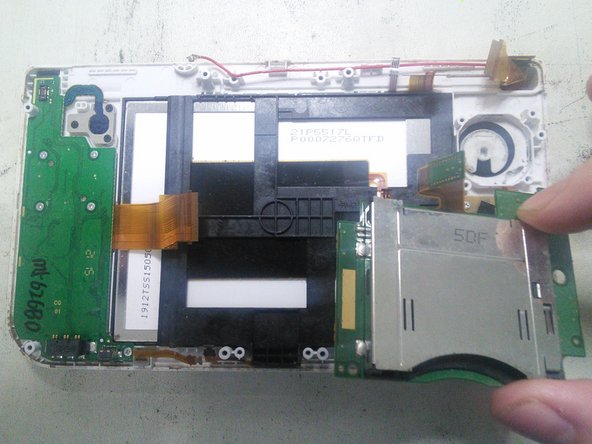
A l'aide d'un tournevis JIS #000 enlevez les 3 vis
-
Retirez ensuite le lecteur de cartouche en le soulevant.
-
-
Questo passaggio è privo di traduzione. Aiuta a tradurlo
-
La pièce marquée en rouge est le support de l'antenne NFC, il faut l'enlever avant d'accéder au bloc LCD/Tactile.
-
Dégagez les clips du support plastique de l'antenne NFC à l'aide d'un outil fin sur le haut et le bas puis détachez-le.
-
-
Questo passaggio è privo di traduzione. Aiuta a tradurlo
-
Glissez un outil plat entre le support noir du LCD/Tactile et le boitier de la console puis soulevez-le doucement. Glissez ensuite un médiator en dessous pour le maintenir.
-
Ensuite, vous pouvez soit soulever l'ensemble en le poussant par dessous, soit continuer à faire le tour pour déclipser l'ensemble et l'extraire.
C’est ça quand on fait de la technique et de la musique !! Effectivement, c’est bien un mediator !!
-
-
Questo passaggio è privo di traduzione. Aiuta a tradurlo
-
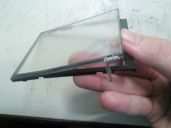
Glissez un outil fin entre le LCD et le boitier noir de l'ensemble puis soulevez doucement. Le LCD devrait sortir sans forcer.
-
-
Questo passaggio è privo di traduzione. Aiuta a tradurlo
-
Chauffez les contours du tactile pour le décoller plus facilement puis poussez le doucement par dessous avec vos doigts pour l'extraire.
-


Annulla: non ho completato questa guida.
Altre 15 persone hanno completato questa guida.

Team

12 Commenti
I followed this guide to the letter last night on my hyrule gold new 3ds XL (from hence forth I will refer to this unit as my “old n3dsXL”) before attempting the same repair on my new unit. It worked fine on my old n3dsXL. So I went ahead with doing the same repair on my new unit.
Well it went fine till I tried to turn it on. The blue light comes on then after a few seconds there’s a “pop” sound and the unit turns back off. Can anyone tell me what just happened here?
Also tried putting the original touch screen back in the new unit and it still does the same pop sound and shuts off
You might need to reseat the cables i had this issue on my old ds lite and my old n3ds all i had to do was that and it fixed it for me also if that doesn’t work get a cotton swab and dip it in rubbing alcohol and clean the end of the ribbon cables then re insert them.
Same thing happened to me my first time—brief blue light but would not power on. Tore it down and re-connected all the cables more carefully the second time. That fixed it.
BBW -
I just disassembled my new 3ds xl to clean my lower screen and touch sensor following this guide, it went smoothly but now everything works except the touch sensor, why??
I have done this successfully three times now—thank you for the excellent guide. Newcomers should know there is one ERROR and one OMISSION in the procedure. (1) ERROR - In Step 13, the topmost ZIF connector marked in red *does* have a clamp, unlike the other four. If you attempt to pull the connector loose without opening the clamp you will break it—see the frustrated comments to Step 13 for examples. (2) OMISSION - At Step 16, before removing the cartridge drive you must unplug the connector at the top of the component. This is shown as unplugged in the photo, but the step is missing from the written instructions. The clamp on this plug loosens on the *opposite* side from where the cable is inserted, unlike the other clamps in the guide.
i used the guide and broke the digitizer and i didn’t have the plastic thing on my model. the galaxy style.
No you do not have to disassamble the digitizer if you only want to change the LCD.
I just want to swap out lcd screens, what steps can I omit? this is the only bottom screen guide online and so many bricks wtf can’t someone make a video like top lcds there are many.
I just need to clean around the touchscreen because all of the bottom section buttons have stopped working. I’ve gotten everything taken apart, but the instructions don’t mention a double sticky tape that is between the touchscreen and the case. In my case, the double sticky tape came up and twisted so that it is now unusable, I can’t seem to find the double sticky tape mentioned on any sites. How do, or can, I buy a replacement? Do I have to buy a completely new touchscreen just to replace the double sticky tape?
It’s the Tessa tape sold here.