Introduzione
Replace a broken display data cable to restore LCD functionality.
Cosa ti serve
-
-
Orient the computer so that the side with the line of screws on it is away from you.
-
Use your thumbs to push both battery release tabs away so that the edge of the battery lifts up.
-
Lift the battery out of the computer.
-
-
-
Loosen the trackpad connector by pulling the locking bar toward the battery housing, using the tips of your fingers.
-
Slide the trackpad cable out of the loosened connector.
-
Note: When reassembling the case, the trackpad cable can get stuck below the slot to the motherboard. It's possible to nudge it out slowly by gently prodding it on either side with a small screwdriver. You don't need to use much force to do this. Eventually it will just pop back out and you can reconnect as per the instructions above. Also, note that the locking bar comes loose so if you see a little piece of plastic lying around when reassembling, that's what it is. :)
-
-
-
Remove the following 10 screws from the bottom case:
-
Three 1.7 mm Phillips from the front edge of the battery compartment.
-
One 3.9 mm T8 Torx to the right of the memory card.
-
One 6.9 mm T8 Torx at the left edge of the memory compartment.
-
Three 12.4 mm fully threaded Phillips from the center of the row of screws along the back edge of the case.
-
Two 15.1 mm 2.5 mm threaded Phillips, one from either end of the row of screws along the back edge of the case.
-
-
-
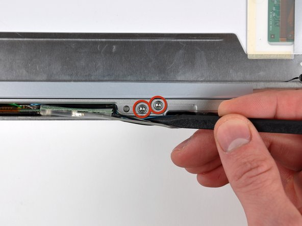
Disconnect the inverter cable, the Bluetooth/DC-In cable, and the display data cable from the logic board.
-
-
-
-
From each complete hinge assembly, remove two Torx T6 screws from the outside of each set, leaving two remaining in the middle of each hinge. On each side, the two screws closer to the edge of the computer are shorter than the two screws closer to the center of the computer. Then remove the two inner screws from each hinge assembly. There are 8 screws total.
-
-
-
When reassembling the display, check to see that the hinges are seated properly before reinstalling the 8 screws of the two hinges. There is a metal phalange on the inside end of each hinge assembly that must be pointed downward and fit into a slot below the inside edge of the hinge. If not, the inside end of each hinge will sit too high and the plastic retaining bracket for the wiring will not sit down properly.
-
-
-
Remove the single Phillips screw from the lower left and right corners of the display.
-
-
-
Insert the flat end of a spudger between the front display bezel and the plastic rim attached to the rear bezel near the lower right corner of the display.
-
While carefully prying the rear display bezel away from the display assembly, use a small flathead screwdriver to pry the small steel clip nearest the bottom right corner of the display away from the edge of the front display bezel.
-
Repeat the above procedure until you've released all the clips along the right side of the display.
-
-
-
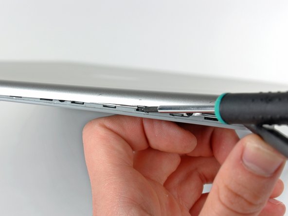
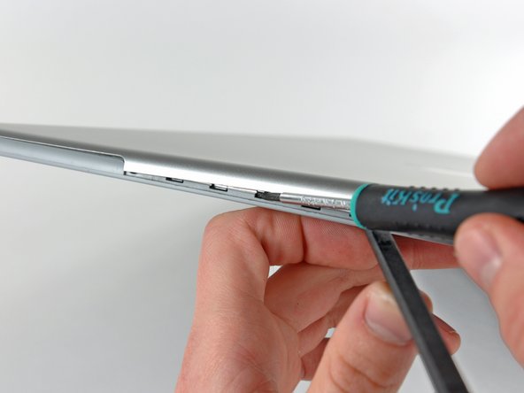
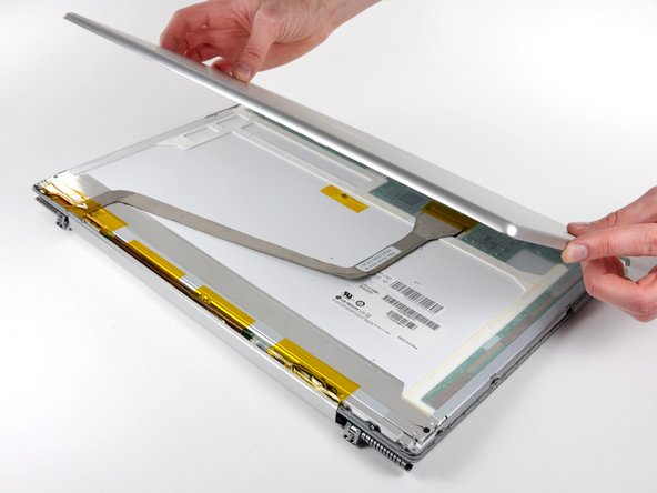
Remove the pieces of tape along the lower edge of the display that are covering the opening of the clutch hinges.
-


To reassemble your device, follow these instructions in reverse order.
To reassemble your device, follow these instructions in reverse order.
Annulla: non ho completato questa guida.
Altre 5 persone hanno completato questa guida.
Documenti Allegati

2 Commenti
The clips that hold the top lid on can be VERY tricky to release if you don't understand how they work first time, once you have released one, the rest are easy! Spotting where you have to pry the clip from with a VERY thin flat head screwdriver from can be tricky because it is exactly the same color as the background and the gap you have to put the screwdriver into can be missed as a result. Don't try any other clips along the side until you have fully released and understood how the first one nearest the corner works.
Step 19 through 25 takes more time trying to figure out the instructions than to actually complete the task because of the confusing use of the words "display bezel" when describing the rear cover and the front LCD panel assembly. After finishing the job I went back to the instructions and crossed out all "rear display bezel" words and changed to "rear cover" and all "front display bezel" words and changed to "front display panel" or "front display assembly". In step 21, I changed the wording to read "between the front display panel plastic rim and the rear cover". In step 22, it now reads "recently-freed right corner of the rear cover". Everything now makes more sense and is easier to understand. Other than that, it went quite well. Now the display no longer fails. It is a poor design on the part of Apple for not figuring out a way to extend the cable further along the hinge line before attaching it to the front display panel. I'm sure the failure occurs at the short section where it flexes at the hinge between the computer and the display.