Questa versione può contenere modifiche errate. Passa all'ultima istantanea verificata.
Cosa ti serve
-
-
Usa una moneta per ruotare la vite di bloccaggio della batteria di 90° in senso orario.
-
Rimuovi la batteria dal computer.
-
-
-
Rimuovi le seguenti 10 viti:
-
Due viti a croce Philips di 3 mm nel vano della batteria, da entrambi i lati dei contatti della batteria.
-
Quatto viti a croce Philips di 3 mm intorno al vano della memoria.
-
Quattro viti a croce Philips di 16 mm lungo la cerniera.
-
-
-
Ruota il computer di 90° gradi in senso orario in modo che le porte siano rivolte verso di te.
-
Rimuovi le tre viti a croce Philips di 3 mm lungo l'estremità del case inferiore.
-
Quando sostituisci queste viti, devi installarle in ordine corretto. Inizia installando la vite più vicina alla cerniera del display, quindi procedi verso la parte anteriore del computer. In più, fai attenzione a non inserire le viti nei due fori su entrambi i lati della porta di uscita video.
-
-
-
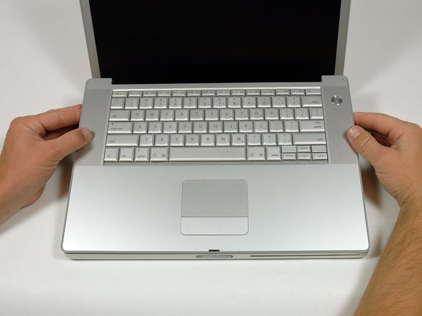
Impugna gli angoli posteriori del case superiore e tira verso l'alto.
-
Solleva la parte posteriore del case e muovi le dita lungo i lati, sbloccando il case mentre procedi. Quando hai sbloccato i lati, potresti dover scuotere il case su e giù per sbloccare la parte anteriore del case superiore.
-
-
-
Rimuovi le due viti a croce Philips di 3 mm che fissano il sensore di luce ambientale sinistro. Una è d'argento e una è nera, o entrambe nere.
-
Scollega il cavo dalla scheda logica per rimuovere il sensore di luce ambientale sinistro dal tuo computer.
-
-
-
-
Rimuovi il dado esagonale di 4 mm che fissa l'altoparlante sinistro.
-
-
-
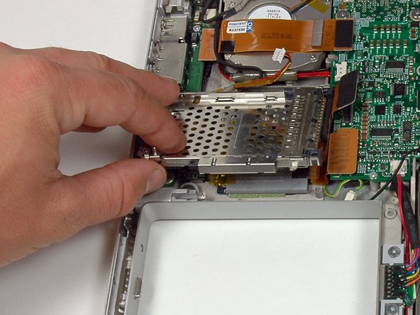
Rimuovi le quattro viti a croce Philips dallo scomparto della scheda PC.
-
-
Questo passaggio è privo di traduzione. Aiuta a tradurlo
-
Close the display and turn the hinge side of the computer to face you.
-
Remove the remaining 5.2 mm Phillips screws on either side of the hinge (two screws total).
-
-
Questo passaggio è privo di traduzione. Aiuta a tradurlo
-
Remove the upper two full thread 10 mm T8 Torx screws from each side of the display, then the two lower shanked 13 mm screws (four screws total).
-
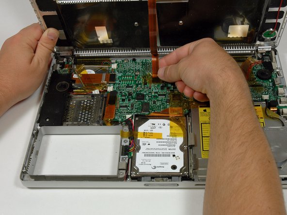
Disconnect the two antenna cables from the airport/bluetooth card (shown in yellow circles), as well as the display cable (wide connector right hand upper corner) and the cable on top left corner of the logic board (shown in blue square).
-
-
Questo passaggio è privo di traduzione. Aiuta a tradurlo
-
Lift the display assembly off the lower case.
-
-
Questo passaggio è privo di traduzione. Aiuta a tradurlo
-
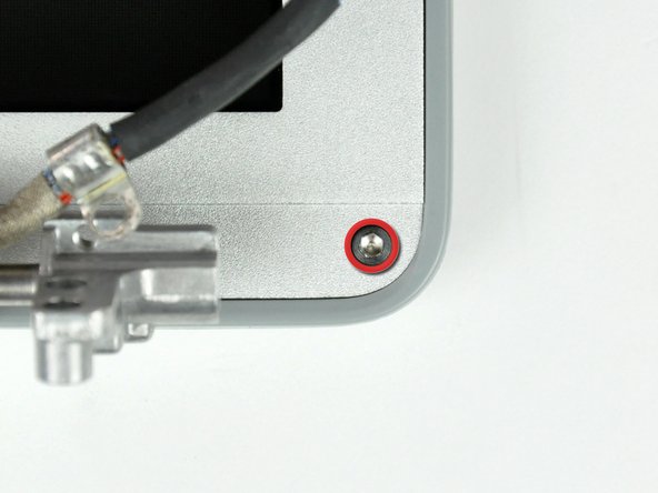
Remove the two 6mm long, 1.5 mm hex screws near the lower left and right corners of the display.
-
-
Questo passaggio è privo di traduzione. Aiuta a tradurlo
-
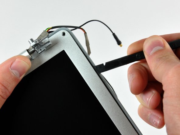
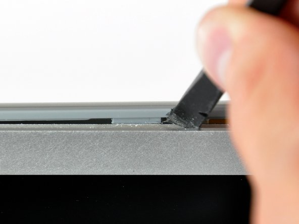
Insert the flat end of a spudger between the front display bezel and the plastic rim attached to the rear bezel near the lower left corner of the display.
-
-
Questo passaggio è privo di traduzione. Aiuta a tradurlo
-
With your spudger still inserted under the front display bezel, run it around the lower left corner of the display.
-
Rotate the spudger away from yourself to pry the rear display bezel off the aluminum tabs on the front display bezel.
-
Work your way down the side of the display until the rear display bezel has been separated from the front display bezel.
-
-
Questo passaggio è privo di traduzione. Aiuta a tradurlo
-
Insert the flat end of a spudger between the rear display bezel and the clutch cover.
-
Twist the spudger to unclip the rear bezel from the clutch cover.
-
-
Questo passaggio è privo di traduzione. Aiuta a tradurlo
-
Repeat the previous steps to separate the right side of the rear display bezel from the display.
-
Use your spudger to pry the plastic retaining clips on the rear display bezel over the raised aluminum tabs on the front display bezel.
-
At this point, the clips on the left and right edges of the rear display bezel should be free from the raised aluminum tabs on the front display bezel. If they are not, use a spudger to pry them past the front display bezel.
-
-
Questo passaggio è privo di traduzione. Aiuta a tradurlo
-
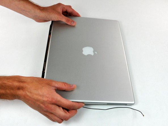
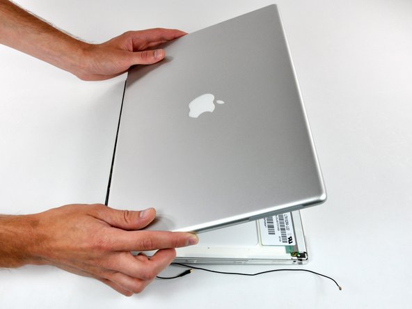
Slightly lift the lower edge of the rear display bezel and push it toward the top edge of the display, releasing the clips along the top edge of the rear display bezel.
-
Rotate the rear display bezel toward yourself and lay it flat on the table.
-
-
Questo passaggio è privo di traduzione. Aiuta a tradurlo
-
Disconnect both antenna cables from the rear display bezel.
-
Remove the rear display bezel and set it aside.
-
-
Questo passaggio è privo di traduzione. Aiuta a tradurlo
-
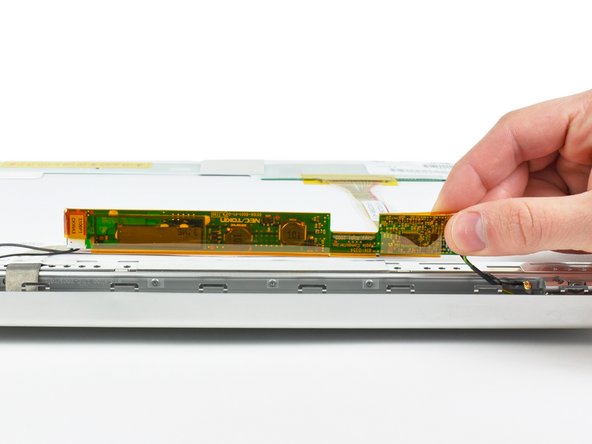
Use a spudger to raise the end of the inverter out from the clutch cover.
-
Lift the inverter enough to access both cable connectors.
-
-
Questo passaggio è privo di traduzione. Aiuta a tradurlo
-
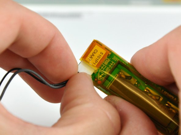
Disconnect both inverter cables by pulling their connectors away from the sockets on the inverter.
-
Remove the inverter from your display and set it aside.
-
-
Questo passaggio è privo di traduzione. Aiuta a tradurlo
-
Remove the five 2 mm Phillips screws securing the LCD retaining bracket to the front display bezel.
-
Lift the LCD retaining bracket off the front display bezel.
-
-
Questo passaggio è privo di traduzione. Aiuta a tradurlo
-
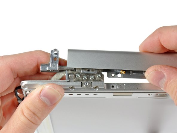
Use your thumbs to push the clutch cover away from the clutch hinges.
-
While pressing with your thumbs, rotate the clutch cover toward yourself about its long edge to pop it off the clutch hinge.
-
-
Questo passaggio è privo di traduzione. Aiuta a tradurlo
-
Repeat this process for the other side of the clutch cover. Once the clutch cover is completely free from the clutch hinges, lift it off the front display bezel.
-