Questa versione può contenere modifiche errate. Passa all'ultima istantanea verificata.
Cosa ti serve
-
Questo passaggio è privo di traduzione. Aiuta a tradurlo
-
Use a coin or a spudger to turn the battery locking screw 90 degrees clockwise.
-
Lift the battery out of the computer.
-
-
Questo passaggio è privo di traduzione. Aiuta a tradurlo
-
Remove the four Phillips screws from the memory door.
-
Slide the memory door away from the memory compartment.
-
-
Questo passaggio è privo di traduzione. Aiuta a tradurlo
-
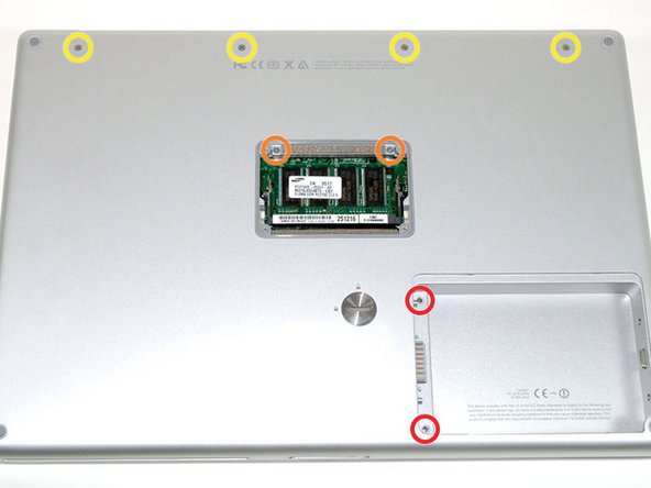
Remove the following 8 screws:
-
Two 3 mm Phillips in the battery compartment, on either side of the battery contacts.
-
Two 12 mm Phillips on either side of the memory compartment.
-
Four 16 mm Phillips along the hinge.
-
-
Questo passaggio è privo di traduzione. Aiuta a tradurlo
-
Rotate the computer 90 degrees clockwise, so that the power receptacle faces you.
-
Remove the three 3 mm Phillips screws.
-
-
-
Questo passaggio è privo di traduzione. Aiuta a tradurlo
-
Turn the computer 90 degrees clockwise so that the hinge faces you.
-
Remove the bottom 5 mm Phillips screw on either side of the hinge (two total).
-
-
Questo passaggio è privo di traduzione. Aiuta a tradurlo
-
Rotate the computer 90 degrees clockwise, so that the ports face you.
-
Remove the three 3 mm Phillips screws.
-
-
Questo passaggio è privo di traduzione. Aiuta a tradurlo
-
Turn the computer over and open the display.
-
Remove the two 1.5 mm hex screws in either corner, next to the display (a T6 Torx driver will work, but repeated use will strip the screws).
-
-
Questo passaggio è privo di traduzione. Aiuta a tradurlo
-
Grasp the back corners of the upper case and pull up. Do not pull the upper case off yet; you still need to disconnect the keyboard and trackpad cable.
-
Lift the back of the case up and work your fingers along the sides, freeing the case as you go. Once you have freed the sides, you may need to rock the case up and down to free the front of the upper case.
-
-
Questo passaggio è privo di traduzione. Aiuta a tradurlo
-
Rotate the upper case up and toward the screen, so that the upper case rests against it.
-
-
Questo passaggio è privo di traduzione. Aiuta a tradurlo
-
Remove the orange tape securing the trackpad ribbon to the logic board.
-
Disconnect the trackpad ribbon from the logic board.
-
Remove the upper case from the computer.
-


Annulla: non ho completato questa guida.
Altre 8 persone hanno completato questa guida.
